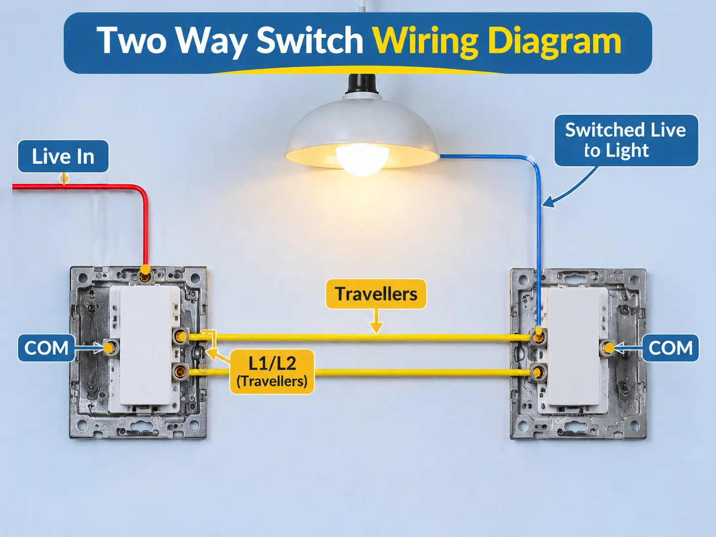
كلا المفتاحين يتحكمان في نفس الضوء ويقعان في نهايات متقابلة من الدرج، أو في نهاية الممر، أو في المرآب. عند النظر لأول مرة إلى الأسلاك، قد يكون الأمر محيرًا قليلاً لأن الأسلاك لا تقوم ببساطة بالتبديل بين التشغيل/الإيقاف مثل المفتاح الأساسي، بل يجب تصورها كدائرة تحكم واحدة.
إجابة سريعة: أسرع طريقة لفهم ذلك هي تذكر أن هناك 3 وصلات على مفتاح ذو اتجاهين؛ سيكون هناك وصلة مشتركة و 2 موصلات ربط. الوصلة المشتركة (COM) تتصل بالتيار الحي للمفتاح الأول، التيار الحي المتحول يتصل بالضوء ويعود من الوصلة المشتركة (COM) للمفتاح الثاني، والوصلة الأخرى تُسمى “المسافر” (L1/L2) وتربط المسافرين من المفتاح الأول إلى الثاني.
تناقش الأقسام التالية ما صُممت له الدائرة، كيفية تجنب فخاخ المصطلحات، ترتيب الأسلاك في الصندوق، توفير 3 طرق للتوصيل وتسلسل إجراء الوصلات، شرح زوج المسافرين والتسمية الصحيحة للأطراف وكيفية اختبار الوظيفة قبل تشغيل الدائرة، وصف الأخطاء الشائعة التي تمثل 90% من جميع الأعطال، اختيار المفتاح والكابل المناسبين، ومراجعة مجموعة منتجاتنا.
ما تفعله دائرة ذو اتجاهين فعليًا
في حالة نظام التبديل ذو الاتجاهين، هناك نقطة اتصال مشتركة على المفتاح تتصل بأحد موصلات الربط وتسمح لك بالتبديل من موصل ربط إلى آخر عن طريق قلب المفتاح لأعلى أو لأسفل. لا توجد وضعيات إيقاف على المفاتيح.
عندما يتم توصيل مفتاحين ذو اتجاهين على التوالي لتزويد الطاقة لنفس الحمل، يمر التيار عبر الطرف المشترك إلى الضوء في كلا الطرفين والاتصال بالضوء هو نفسه. هذا يسمح للمفتاحين بالاستمرار في توفير الطاقة للحمل أو قطع الدائرة، اعتمادًا على وضعية المفاتيح. لذلك، يمكن لأي من المفتاحين تشغيل الدائرة أو إيقافها بغض النظر عن حالة المفتاح الآخر.
لهذا السبب، الفرق الوحيد بين تكوين الأسلاك ذو الاتجاهين وتكوين الأسلاك ذو الاتجاه الواحد هو أن دائرة ذو الاتجاهين تحتوي على موصل إضافي مقارنة بدائرة ذو الاتجاه الواحد. الموصل الإضافي هو ما يجعل دائرة ذو الاتجاهين أكثر تكلفة من دائرة ذو الاتجاه الواحد، وهو السبب في أن دائرة ذو اتجاه واحد موجودة يمكن تحويلها إلى دائرة ذو اتجاهين فقط عن طريق تمديد كابل جديد.
ارتباك المصطلحات: ذو اتجاهين، ذو ثلاثة اتجاهات، وذو أربعة اتجاهات
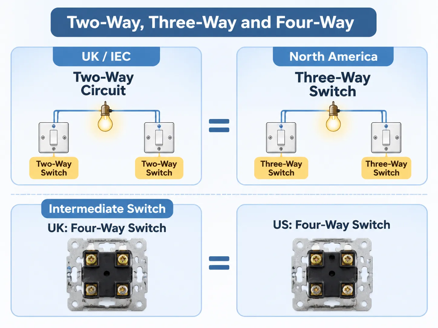
تُعرف دوائر التبديل ذو الاتجاهين بأسماء مختلفة حسب الجانب الذي تتواجد فيه من المحيط، وخلط هذه المصطلحات هو المصدر الأكثر شيوعًا للأخطاء في هذه المهنة. على سبيل المثال، في المملكة المتحدة وIEC، يُشار إلى مفتاحين متصلين بنفس الضوء على أنه دائرة ذو اتجاهين, ، بينما في أمريكا الشمالية يُشار إلى تكوين دائرة مفتاحين باسم “مفتاح ثلاثي الاتجاهات”، حيث يوجد ثلاثة أطراف على المفتاح. اتصال المفتاح الوسيط لكل من تلك الدوائر هو “مفتاح رباعي الاتجاهات”، والذي يحتوي أيضًا على أربعة أطراف. لذلك، على الرغم من أن كلاهما يُسمى بشكل مختلف، إلا أنه لا يهم أيهما صحيح.
بالإضافة إلى ذلك، اعتمادًا على ما إذا كنت تبحث عن مخطط لـ “مفتاح ثنائي الاتجاه” من مصدر بريطاني أو “مفتاح ثلاثي الاتجاهات” من مصدر أمريكي، ستجد أنهما يصفان نفس تكوين الأسلاك. وبالتالي، عند مقارنة مفاتيح الاتجاهين والثلاثة، من المهم قراءة كلا المخططين لفهم كيفية ارتباطهما ببعضهما البعض؛ ستكون علامات الأطراف لمفتاح ثنائي الاتجاه بريطاني مختلفة عن تلك الخاصة بمفتاح ثلاثي الاتجاهات أمريكي.
الأسلاك داخل الصندوق وما هو كل منها
يجب تمثيل الوظائف الأربع التالية عند المفتاح في كل من مواقع المفاتيح:
- التغذية المستمرة (أي الإمداد) للدائرة؛;
- التغذية المتحكم بها (أو الحي المتحكم به) إلى جهاز الإضاءة؛;
- سلكا السفر اللذان يربطان المفتاح بكل من المفاتيح (سلك المسافر); ؛ و
- السلك المحايد. هذا السلك لا يتصل فعليًا بأي من المفاتيح ولكنه يجب أن يصل إلى جهاز الإضاءة.
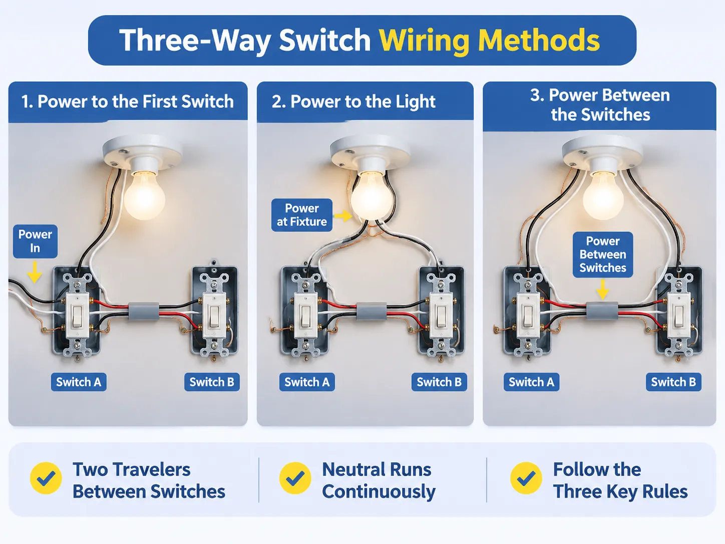
سيختلف مظهر الأسلاك داخل الصندوق بناءً على طريقة التوصيل. في الطريقة البريطانية الأكثر شيوعًا للتوصيل، المسماة loop in، تنتهي أسلاك الإمداد والمحايد عند وردة السقف ويذهب كابل ثلاثي النوى إلى كل من المفاتيح. بالمقابل، قد يدخل الإمداد عند أحد المفاتيح في طريقة التوصيل الأمريكية، ويتم تشغيل كابل ثلاثي الموصلات من هناك إلى المفتاح الثاني. يربط كابل ثلاثي الموصلات كل من المفاتيح بجهاز الإضاءة المقابل.
بالإضافة إلى ذلك، سيكون سلك الأرضي دائمًا منفصلًا.
الطريقة الأولى لتوصيل مفاتيح ثلاثية الاتجاهات هي أخذ الطاقة إلى المفتاح الأول ثم تشغيلها إلى المفتاح الثاني ثم إلى الضوء.
طريقة التوصيل 1: الطاقة إلى المفتاح الأول
بأخذ كل الطاقة إلى صندوق واحد سيكون كل شيء متصلًا به مباشرة. لذلك، عند توصيل سلك الإمداد الخاص بك إلى المفتاح A، فأنت في الواقع توصل هذا السلك كما يلي: الموصل الحي يذهب مباشرة إلى الطرف المشترك؛ (الطرف الموسوم بنقطة سوداء) الموصل المحايد يتم توصيله بين المفتاح A والضوء؛ (الطرف الموسوم بنقطة بيضاء) وموصل الأرضي يذهب من المفتاح A إلى الصندوق وإلى لوحة المفتاح.
في هذه الطريقة، من المفتاح A إلى المفتاح B ستقوم بتشغيل كابل ثلاثي الأسلاك. يتم توصيل السلكين الأولين L1 إلى L1 و L2 إلى L2. السلك الثالث سيصبح السلك الحي المتحكم به؛ سيتصل بالطرف المشترك للمفتاح B قبل أن يستمر في تغذية الطاقة إلى جهاز الإضاءة.
في الجهاز، سيتصل المصباح بالسلك الحي المتحكم به والموصل المحايد القادم من المفتاح A. يجب ألا يكون لجهازك اتصال مباشر بأي مصدر طاقة آخر غير ما يزوده المفتاح/الصمامات.
مع هذه الطريقة في توصيل مفاتيح الثلاثة اتجاهات، من المفيد توصيل أسلاك المسافر أولاً؛ ثم توصيل المشترك والمحايد لإكمال الدائرة. مخطط توصيل مفتاح الثلاثة اتجاهات يستخدم اتفاقيات الألوان في أمريكا الشمالية وسيُظهر لك كيفية توصيل هذا التكوين إذا كان الكابل الذي تستخدمه أسود، أحمر وأبيض، بالإضافة إلى سلك الأرضي العاري.
طريقة التوصيل 2: الطاقة إلى المصباح
عند التجهيز، يتم توصيل السلك الحار الدائم إلى موصل من سلك المفتاح الأول لإنشاء الحار الدائم إلى المفتاح A. كما يتم توصيل السلك المحايد إلى التجهيز. يذهب سلك المفتاح الثاني من التجهيز عائدًا إلى المفتاح B مع موصلين إضافيين هما أسلاك المسافر المتجهة إلى المفتاح B.
وفقًا للكود، يجب أن تتم جميع التوصيلات عند التجهيز داخل صندوق وصول يمكن الوصول إليه بدلاً من تغليفه داخل فراغ السقف. بالإضافة إلى ذلك، يجب تجنب الوصلات المغلفة بالشريط لأنها قد تشكل مصدر فشل محتمل عند وجود رطوبة في فراغ السقف.
طريقة التوصيل 3: الطاقة بين المفاتيح
هذه طريقة شائعة في التركيبات التجارية وبناء الجدران الحجرية. يتم تمرير كابل ثلاثي النوى واحد بين المفتاحين ولكل مفتاح كابل ثنائي النوى خاص به إلى التجهيز. بدلاً من ذلك، يمكن توصيل التجهيز في حلقة عبر المفاتيح.
الميزة في هذه الطريقة هي أنه يلزم كابل واحد فقط يمر عبر الغرفة، وهذا مهم عند تمرير الكابل عبر جدار صلب. العيب في هذه الطريقة هو أن إجراء التوصيلات عند المفاتيح يصبح أكثر تعقيدًا حيث يجب توصيل السلك الحار الدائم، السلك الحار المتحول، والأسلاك المسافرة الأربعة في نفس الصندوق.
بغض النظر عن الطريقة التي تستخدمها، هناك سلكان مسافران بين المفاتيح، والمشتركان في كل مفتاح سيتصلان إما بالمصدر أو بالتجهيز، والمحايد سيمر دون انقطاع من المصدر إلى المصباح.
أي رسم لا يتوافق مع أي من القواعد الثلاثة غير صحيح بغض النظر عن تكوينه.
علامات الأطراف وطريقة التوصيل
تستخدم أنواع مختلفة من المنتجات علامات أطراف مختلفة، اعتمادًا على المنطقة، وإذا قمت بتوصيل طرف بشكل غير صحيح، فقد يعمل فقط بشكل صحيح عندما يكون المفتاح في أحد المواضع.
| الطرف (بريطاني / IEC) | العلامة في أمريكا الشمالية | مكان التوصيل |
|---|---|---|
| المشترك — COM أو C | برغي أسود أو داكن معلم بـ “Common” | الحي إلى المفتاح A، الضوء إلى المفتاح B |
| المسافر 1 — L1 | برغي نحاسي معلم بـ “Traveller 1” | L1 on other switch |
| Traveller 2 — L2 | Brass screw labelled “Traveller 2” | L2 on other switch |
| Earth — E or Earth Symbol | برغي أخضر | To the box and plate |
When connecting a pair of travellers, they must remain connected continuously; i.e. L1 to L1 and L2 to L2. If they are crossed it will produce a situation whereby both switches must be in the same position (the incorrect way to wire a two-way circuit).
The terminals on two-gang two-way switches are arranged in the same way, with two commons at one end of the panel. The slim panel version of the two-gang two-way switch is the layout that is most commonly used by European contractors, and it uses the same logic as the two-gang two-way switch.
Testing Before You Energise
You must complete three tests in the following order before you apply supply voltage:
1) Continuity of Travellers – to verify that the pair have not been crossed and are not broken.
2) Continuity of Earth – to verify the safety path has a continuous connection from the Plate to the Box.
3) The insulation resistance is measured between the live and neutral conductors as well as the live and earth conductors. It is important to check these resistances prior to connecting the supply to ensure they are both normal (i.e., greater than 2MΩ). If they are not normal, it indicates possible damage due to a pinched conductor that has not yet caused a fault.
Once the circuit has been energized, it is important to check both switches (i.e., switch A and switch B) in all four possible positions (i.e., A up and B up, A up and B down, A down and B up and A down and B down). The correct operation of a two-way circuit is confirmed when the light responds as it should in all four possible configurations, which demonstrates that the two switches operate the circuit in the same way (i.e., turning it on and off). The state of the light when tested with both switches in opposite orientations can also be used to verify the circuit can correctly change between states.
| Switch A | Switch B | Light | What it proves |
|---|---|---|---|
| Up | Up | On | Both are on the same path, so the circuit is complete |
| Up | Down | Off | One end changed to the other path, so the circuit opened |
| Down | Up | Off | The other end changed to the other path, so the circuit opened |
| Down | Down | On | Both are on the same path again, and the light is lit on this second path |
If the light operates by either switch alone, the travellers may have crossed or one may be open. If it only works when both switches are in a particular configuration, then the common and one traveller will have swapped their position at one end. If the light does not operate at all but the breaker continues to hold, the supply may have been switched to the wrong terminal.
Where It Goes Wrong: The Six Most Frequent Errors
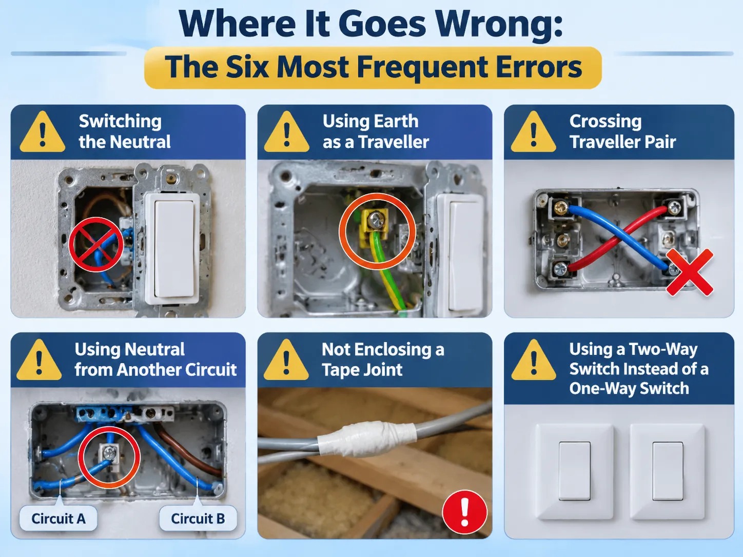
Switching of the Neutral. An error that can often create the most extreme danger, as the light will go out but the fitting will remain live while it is off. A neutral should never be connected to a switch terminal.
The use of Earth as a Traveller. This occurs in some of the older installations, as a three-core cable was unavailable, resulting in the metal body of the fitting being at mains potential.
It is easy for an inspector to tell if the wire continuity test has been completed with a combination tester because the combination tester will show the continuity of each circuit.
Crossing traveller pair. The continuation of circuit operation depends on one traveller being used with each switch, therefore the fault will appear as a continued connection, which can be very confusing.
Using neutral from another circuit. A neutral from another circuit can create a situation where the circuit appears to operate as intended, but if the circuit trips the RCD, there is an issue. More importantly, it is important to remember that sharing a neutral between two circuits constitutes a fault that may only be evident under certain circumstances.
Not enclosing a tape joint in the void above the ceiling. Not enclosing a taped joint can create a code violation as well as a fire hazard and will remain invisible until it fails.
Using a two-way switch where a one-way switch was to be used. When using a one-way switch in the two-way switch circuit, it can only operate from one end of the circuit. If a second person were to open the box, then that person would have to determine why it would not work.
Choosing the Switch and the Cable
Cable for a traveller run is three-core and earth, usually 1.0 or 1.5mm2 for British lighting circuits, or 14/3 and 12/3 for North American circuits. The total number of conductor count is what is important, as cable has two traveller, one switched live, and earth, all in one sheath.
The type of switch must be a two-way (not a one-way) as both will appear to be the same from the front but require a third terminal to complete the circuit. If a one-way switch is used in the two-way circuit, only the one switch will turn on the light. This mistake will not be discovered until the wall is finished.
With circuits using dimmers, there are two types of dimmers: a two-way dimmer and a one-way dimmer. Only one of the two positions of the circuit dimmer can be used for dimming, unless a remote control to a master switch is being used (this allows the user to control the dimming from either location). If a project is going to order the plate (the mounting area) to match the rest of the installation, it must order the same type of plate (two-way mechanism) as the other switches being used in the project.
مكان GOG
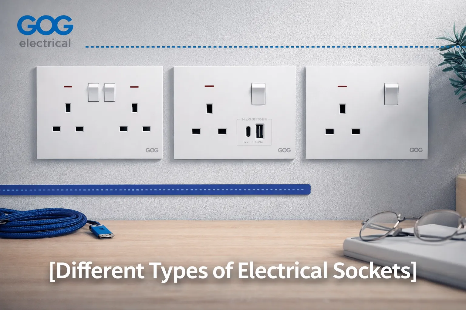
In addition to supporting the installation of one-way, two-way and intermediate switches for your application, GOG provides the opportunity to standardise the look and feel of the two-way switch throughout the entire installation. One of the key benefits of the two-way switch is that it exists in every room that has two doors. In a project with three different plate families, there may be numerous spare parts available for every project.
Although we provide the switches to build a project around, we cannot design the circuit. The circuit route (cable), the circuit protection device (circuit breaker) and the circuit inspection/auditing (compliance) will be the responsibility of the electrician and these organisations will not consider the switch to be part of their work, rather they will consider the switch as a component of their work.
الأسئلة المتكررة
Where do you connect the wires to a two-way light switch?
Attach the permanent live to the common terminal of the first switch, and the switched live to the lamp is connected to the common terminal of the second switch. The 2 traveller wires connect L1 to L1 and L2 to L2. A neutral wire is not connected to either switch and directly connects to the lamp; the earth wire connects to the earth terminals on both ends of the switch box and the switch plate.
How do I wire a 2-way switch?
You will run a 3 core and earth cable between the 2 switch locations, a supply cable to 1 switch, and a switched live and neutral to the lamp. The travellers are connected L1-L1, L2-L2, supply to the common of the first switch, lamp to the common of the second switch, and the neutral continues through uninterrupted. You should ensure that the wiring has continuity before connecting to power.
How do I determine if I need a 2-way switch or a 3-way switch?
The number of locations from which you want to control the lamp(s) determines the appropriate switch type. A single switch controls a lamp from 1 location; 2 switches control a lamp from 2 locations (known in the UK as a 2-way switch; in Canada and the USA as a 3-way switch). To control 3 or more lamp locations requires an intermediate/4-way switch in the run.
How do I wire a 2-way switch using a 3-wireconfiguration?
The switches have three wires running between them, two of which are travellers, while the third wire is a switched live. You would connect each live wire from L1 of the first switch to L1 of the second switch, L2 of the first switch to L2 of the second switch, and the third wire runs from the common (C) of the second switch to the light. If the cable has a fourth wire (bare), that is an earth, so it will go to the box and plate at each end.
Is it possible to use a one-way switch as a two-way?
No, a one-way switch has only two terminating connections. Hence, it cannot divert between two paths, and therefore the second position for switching will not work. The only similarity is the front of the mechanism. Always check the terminal count before making your purchase.
Why does the two-way switch work in only one direction?
Most likely, you are dealing with either crossed traveller pairs, one of the travellers not connected and the common (C) has been misused as a traveller connection for the first part of your question, or two of them are connected to work in one switch position, while the third produces no operation whatsoever. Continuity testing of both switches will help to confirm which of these situations is happening.
المراجع
- Legrand — Wiring Devices and Multiway Switching
- Leviton — Three-Way Switch Wiring and Terminal Markings
- UL Solutions — شهادة أجهزة التوصيل
- NEMA — Ratings of Wiring Devices and Switches
- Electrical Engineering Portal — Lighting Circuit Control Methods
الخاتمة
في دائرة ذات اتجاهين، لدينا محولين في سلسلة مع الأطراف ومصدر الطاقة/الأرضي المشترك/المرجع يتجمعون في الطرف المقابل للدائرة لتزويد الطاقة، بينما الموصلات تربطهم على التوازي، مع توصيل النيوترال مرة أخرى إلى الصندوق.
When creating this circuit, the two items that determine whether it is successful or not are the traveller pairings and the terminal count. If the traveller’s pair is crossed over, the light will work in reverse on one switch and will never work at the second switch position if you go with a one-way switch instead of the two-position switch. Both situations can be easily avoided when purchasing properly, but can be very costly to repair after installation is completed.