Both of these switches control the same light and are located on opposite ends of the staircase, down the hallway or at the garage. When you first look at the wiring it can be a little confusing because the wiring does not simply switch ON/OFF like a basic switch, it has to be visualised as a single control circuit.
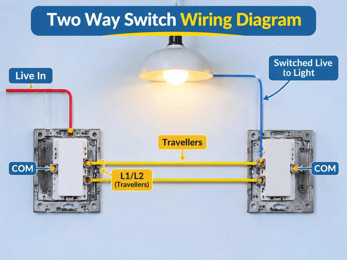
Quick answer: The quickest way to understand it is to remember that there are 3 connections on a two way switch; there will be a common connection and 2 strappers. The common connection (COM) goes to the Live of the first switch, the Switched live goes to the light and comes back from the common connection (COM) of the second switch and the other 2 connections are called “traveller” (L1/L2) and connect travellers from the first switch to the second.
The subsequent sections discuss what the circuit is designed for, how to avoid terminology traps, lay out the wires in a box, provide 3 wiring methods and the sequence in which you should make the connections, explain the traveller pair and correct terminal naming and how to test functioning before energising the circuit, describe the common errors that account for 90% of all failures, selection of the appropriate switch and cable, and review the range of our products.
What a Two-Way Circuit Actually Does
In the case of a two-way switching system, there is a common point of connection on the switch that connects to one of the strappers and allows you to switch from one strap to another by flipping the switch up or down. There are no off positions on the switches.
When two two-way switches are wired in series to supply the power to the same load, there is power going through the common terminal to the light at both ends and the connection to the light is the same. This allows the two switches to continue to provide power to the load or to break the circuit, depending on the position of the switches. Therefore, either switch can turn the circuit on or off, irrespective of the condition of the other switch.
For this reason, the only difference between a two-way and a one-way wiring configuration is that a two-way circuit has one more conductor than a one-way circuit. The extra conductor is what makes a two-way circuit more expensive than a one-way circuit, and it is the reason that an existing one-way circuit can be converted to a two-way circuit only by running a new cable.
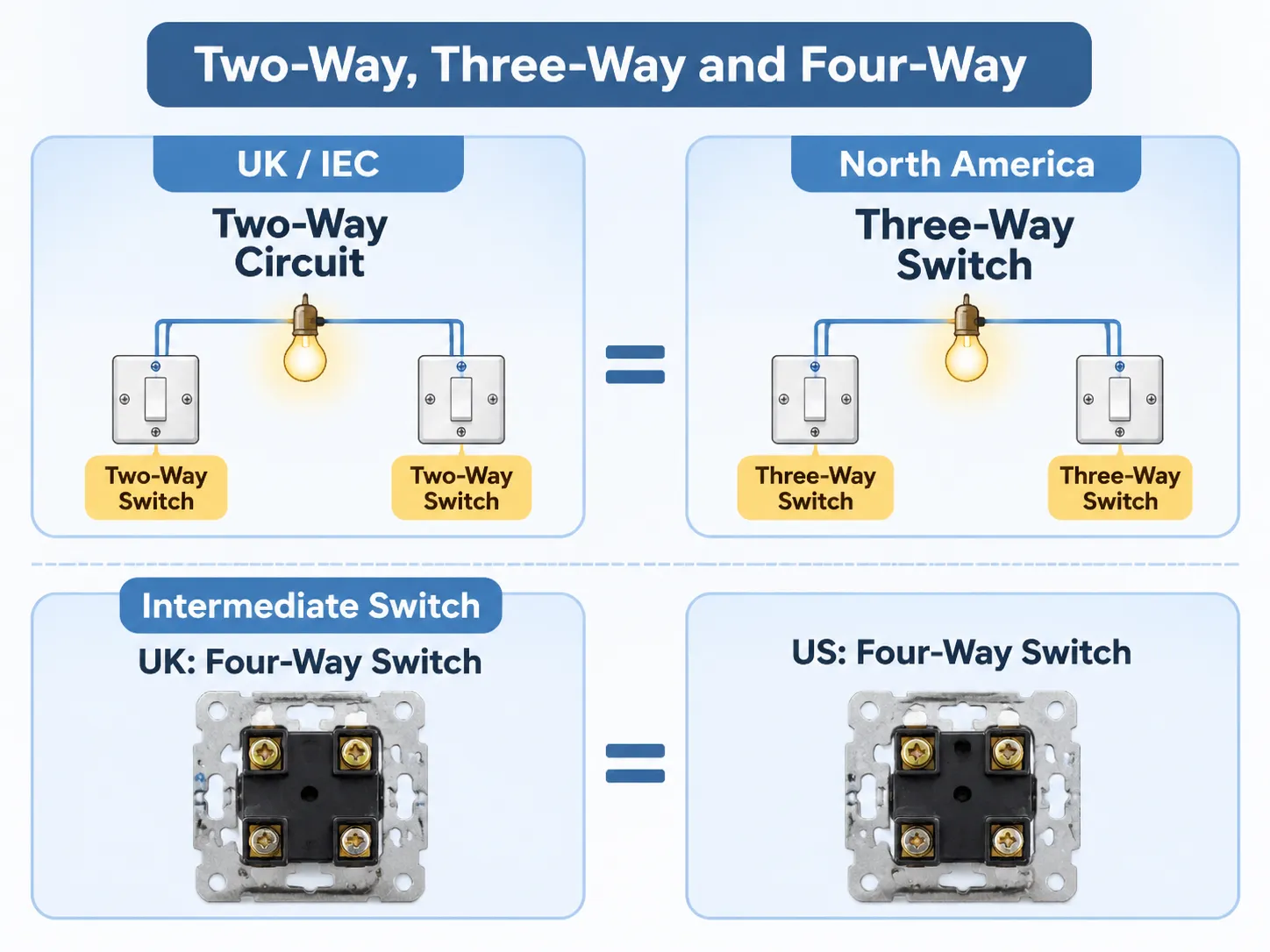
Terminology Confusion: Two-Way, Three-Way and Four-Way
Two-way switching circuits are referred to by different names depending on which side of the ocean you are on, and mixing these terms is the most common source of error in this profession. For example, in the UK and IEC, two switches connected to the same light would be referred to as a two-way circuit, while in North America the configuration for a two-switch circuit is referred to as a “three-way switch”, as there are three terminals on the switch. The intermediate switch connection for each of those circuits is a “four-way switch”, which also contains four terminals. Therefore, although both are named differently, it doesn’t matter which is correct.
In addition, depending on whether you are looking for a diagram of either a “two-way switch” from a UK source or a “three-way switch” from a US source, you will find that they describe the same wiring configuration. Consequently, when comparing two and three way switches, it is important to read both diagrams to understand how they relate to one another; the terminal marking for a British two-way switch will be different than that for a US three-way switch.
The Wires in the Box and What Each One Is
The following four functions must be represented at the switch in each of the switch locations:
- the continuous feed (i.e. supply) to the circuit;
- the switched feed (or switched live) to the light fixture;
- the two travel wires connecting the switch to each of the switches (traveller wire); and
- the neutral wire. This wire does not physically connect to either of the switches but must reach the light fixture.
The appearance of the wires inside the box will differ based on the wiring method. In the most common UK method of wiring, called loop in, the supply and neutral wire terminate at a ceiling rose and the three core cable goes to each of the switches. In contrast, the supply may enter at one of the switches in the North American wiring method, and a three-conductor cable would be run from there to the second switch. A three-conductor cable would connect each of the switches to the corresponding light fixture.
In addition, the earth wire will always be separate.
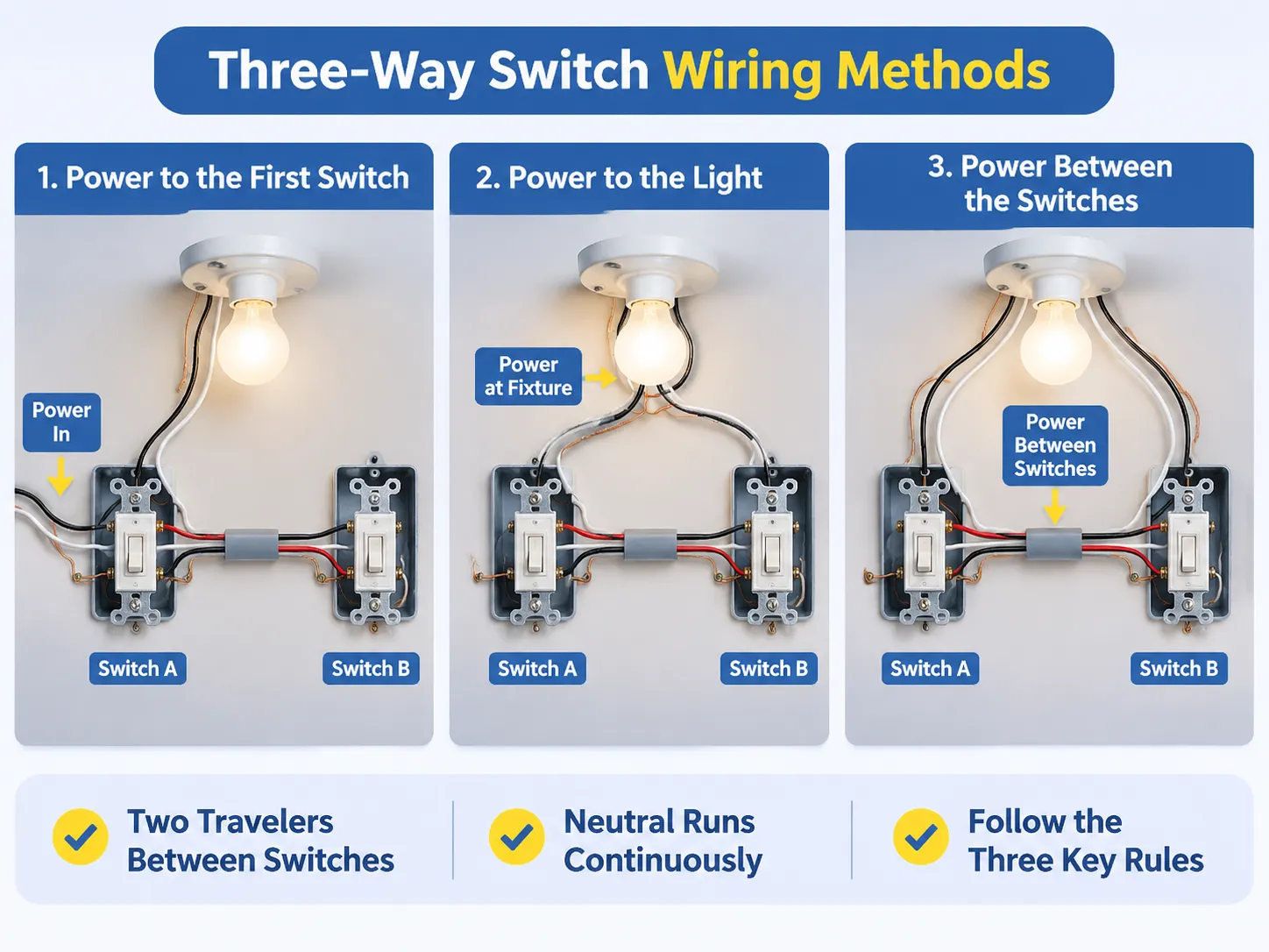
The first method for wiring three-way switches is to take power into the first switch and then run it to the second switch and then to the light.
Wiring Method 1: Power to the First Switch
By taking all power into one box you will have everything connected directly to it. So, when you connect your supply wire into Switch A, you are actually connecting this wire as follows: The live conductor goes directly to the Common terminal; (the terminal marked with a black dot) the Neutral conductor is spliced between Switch A and the light; (the terminal marked with a white dot) and the Earth conductor goes from Switch A to the box and to the switch plate.
In this method, from Switch A to Switch B you will run a 3-wire cable. The first two wires are connected L1 to L1 and L2 to L2. The third wire will become the switched Live wire; it will connect to the Common terminal of Switch B before it continues to feed power into the light fixture.
In the fixture, the light bulb will connect to the switched Live and Neutral conductors coming from Switch A. Your fixture should not have a direct connection to any other power source other than what is supplied by the switch/fuses.
With this method of wiring three-way switches, it is beneficial to wire the traveller wires first; then connect the commons and the neutral through to complete the circuit. The three-way switch wiring diagram uses the North American colour conventions and will show you how to wire this configuration if the cable you are using is black, red and white, plus bare (ground).
Wiring Method 2: Power to the Light
At the fixture, the permanent hot wire is connected to a conductor of the first switch wire to create the permanent hot to switch A. The neutral wire is also connected to the fixture. The second switch wire goes from the fixture back to switch B with an additional two conductors that are the travelers going to switch B.
According to the code, all connections at the fixture must be made in an accessible enclosure rather than being taped off inside of the ceiling void. In addition, taped joints should be avoided as they will create a potential source of failure when moisture is present in the ceiling space.
Wiring Method 3: Power Between the Switches
This is a popular method in commercial installations and masonry wall construction. A single three-core cable is run between the two switches and each switch has its own two-core cable to the fixture. Alternatively, the fixture can be wired in a loop through the switches.
The advantage to this method is that there is only one cable running across the room is needed, this is important when the cable is run through a solid wall. The disadvantage to this method is that making connections at the switches is much more complex as the permanent hot wire, switched hot wire and the two travelers will need to be connected in the same box.
Regardless of which method you use, there are two travelers between the switches, the commons of each switch will either connect to the source or the fixture and the neutral will run uninterrupted from source to lamp.
Any drawing that does not conform to any of the three rules is incorrect regardless of its configuration.
Terminal Markings and Connection Method
Different types of products use different terminal markings, depending on the region, and if you incorrectly connect a terminal, it may only operate correctly when the switch is in one of two positions.
| Terminal (British / IEC) | North American marking | Where it connects |
|---|---|---|
| Common — COM or C | Black or dark screw labelled “Common” | Live to Switch A, Light to Switch B |
| Traveller 1 — L1 | Brass screw labelled “Traveller 1” | L1 on other switch |
| Traveller 2 — L2 | Brass screw labelled “Traveller 2” | L2 on other switch |
| Earth — E or Earth Symbol | Green screw | To the box and plate |
When connecting a pair of travellers, they must remain connected continuously; i.e. L1 to L1 and L2 to L2. If they are crossed it will produce a situation whereby both switches must be in the same position (the incorrect way to wire a two-way circuit).
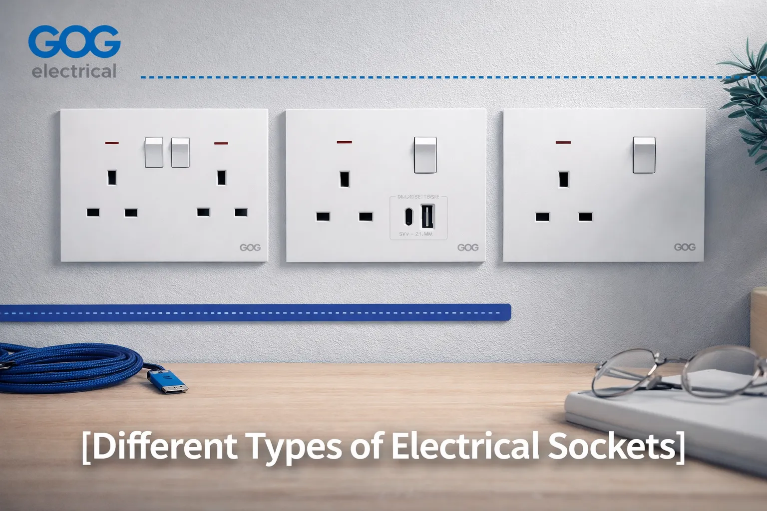
The terminals on two-gang two-way switches are arranged in the same way, with two commons at one end of the panel. The slim panel version of the two-gang two-way switch is the layout that is most commonly used by European contractors, and it uses the same logic as the two-gang two-way switch.
Testing Before You Energise
You must complete three tests in the following order before you apply supply voltage:
1) Continuity of Travellers – to verify that the pair have not been crossed and are not broken.
2) Continuity of Earth – to verify the safety path has a continuous connection from the Plate to the Box.
3) The insulation resistance is measured between the live and neutral conductors as well as the live and earth conductors. It is important to check these resistances prior to connecting the supply to ensure they are both normal (i.e., greater than 2MΩ). If they are not normal, it indicates possible damage due to a pinched conductor that has not yet caused a fault.
Once the circuit has been energized, it is important to check both switches (i.e., switch A and switch B) in all four possible positions (i.e., A up and B up, A up and B down, A down and B up and A down and B down). The correct operation of a two-way circuit is confirmed when the light responds as it should in all four possible configurations, which demonstrates that the two switches operate the circuit in the same way (i.e., turning it on and off). The state of the light when tested with both switches in opposite orientations can also be used to verify the circuit can correctly change between states.
| Switch A | Switch B | Light | What it proves |
|---|---|---|---|
| Up | Up | On | Both are on the same path, so the circuit is complete |
| Up | Down | Off | One end changed to the other path, so the circuit opened |
| Down | Up | Off | The other end changed to the other path, so the circuit opened |
| Down | Down | On | Both are on the same path again, and the light is lit on this second path |
If the light operates by either switch alone, the travellers may have crossed or one may be open. If it only works when both switches are in a particular configuration, then the common and one traveller will have swapped their position at one end. If the light does not operate at all but the breaker continues to hold, the supply may have been switched to the wrong terminal.
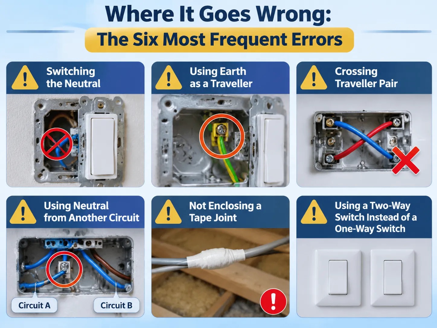
Where It Goes Wrong: The Six Most Frequent Errors
Switching of the Neutral. An error that can often create the most extreme danger, as the light will go out but the fitting will remain live while it is off. A neutral should never be connected to a switch terminal.
The use of Earth as a Traveller. This occurs in some of the older installations, as a three-core cable was unavailable, resulting in the metal body of the fitting being at mains potential.
It is easy for an inspector to tell if the wire continuity test has been completed with a combination tester because the combination tester will show the continuity of each circuit.
Crossing traveller pair. The continuation of circuit operation depends on one traveller being used with each switch, therefore the fault will appear as a continued connection, which can be very confusing.
Using neutral from another circuit. A neutral from another circuit can create a situation where the circuit appears to operate as intended, but if the circuit trips the RCD, there is an issue. More importantly, it is important to remember that sharing a neutral between two circuits constitutes a fault that may only be evident under certain circumstances.
Not enclosing a tape joint in the void above the ceiling. Not enclosing a taped joint can create a code violation as well as a fire hazard and will remain invisible until it fails.
Using a two-way switch where a one-way switch was to be used. When using a one-way switch in the two-way switch circuit, it can only operate from one end of the circuit. If a second person were to open the box, then that person would have to determine why it would not work.
Choosing the Switch and the Cable
Cable for a traveller run is three-core and earth, usually 1.0 or 1.5mm2 for British lighting circuits, or 14/3 and 12/3 for North American circuits. The total number of conductor count is what is important, as cable has two traveller, one switched live, and earth, all in one sheath.
The type of switch must be a two-way (not a one-way) as both will appear to be the same from the front but require a third terminal to complete the circuit. If a one-way switch is used in the two-way circuit, only the one switch will turn on the light. This mistake will not be discovered until the wall is finished.
With circuits using dimmers, there are two types of dimmers: a two-way dimmer and a one-way dimmer. Only one of the two positions of the circuit dimmer can be used for dimming, unless a remote control to a master switch is being used (this allows the user to control the dimming from either location). If a project is going to order the plate (the mounting area) to match the rest of the installation, it must order the same type of plate (two-way mechanism) as the other switches being used in the project.
Where GOG Fits
In addition to supporting the installation of one-way, two-way and intermediate switches for your application, GOG provides the opportunity to standardise the look and feel of the two-way switch throughout the entire installation. One of the key benefits of the two-way switch is that it exists in every room that has two doors. In a project with three different plate families, there may be numerous spare parts available for every project.
Although we provide the switches to build a project around, we cannot design the circuit. The circuit route (cable), the circuit protection device (circuit breaker) and the circuit inspection/auditing (compliance) will be the responsibility of the electrician and these organisations will not consider the switch to be part of their work, rather they will consider the switch as a component of their work.
Frequently Asked Questions
Where do you connect the wires to a two-way light switch?
Attach the permanent live to the common terminal of the first switch, and the switched live to the lamp is connected to the common terminal of the second switch. The 2 traveller wires connect L1 to L1 and L2 to L2. A neutral wire is not connected to either switch and directly connects to the lamp; the earth wire connects to the earth terminals on both ends of the switch box and the switch plate.
How do I wire a 2-way switch?
You will run a 3 core and earth cable between the 2 switch locations, a supply cable to 1 switch, and a switched live and neutral to the lamp. The travellers are connected L1-L1, L2-L2, supply to the common of the first switch, lamp to the common of the second switch, and the neutral continues through uninterrupted. You should ensure that the wiring has continuity before connecting to power.
How do I determine if I need a 2-way switch or a 3-way switch?
The number of locations from which you want to control the lamp(s) determines the appropriate switch type. A single switch controls a lamp from 1 location; 2 switches control a lamp from 2 locations (known in the UK as a 2-way switch; in Canada and the USA as a 3-way switch). To control 3 or more lamp locations requires an intermediate/4-way switch in the run.
How do I wire a 2-way switch using a 3-wireconfiguration?
The switches have three wires running between them, two of which are travellers, while the third wire is a switched live. You would connect each live wire from L1 of the first switch to L1 of the second switch, L2 of the first switch to L2 of the second switch, and the third wire runs from the common (C) of the second switch to the light. If the cable has a fourth wire (bare), that is an earth, so it will go to the box and plate at each end.
Is it possible to use a one-way switch as a two-way?
No, a one-way switch has only two terminating connections. Hence, it cannot divert between two paths, and therefore the second position for switching will not work. The only similarity is the front of the mechanism. Always check the terminal count before making your purchase.
Why does the two-way switch work in only one direction?
Most likely, you are dealing with either crossed traveller pairs, one of the travellers not connected and the common (C) has been misused as a traveller connection for the first part of your question, or two of them are connected to work in one switch position, while the third produces no operation whatsoever. Continuity testing of both switches will help to confirm which of these situations is happening.
References
- Legrand — Wiring Devices and Multiway Switching
- Leviton — Three-Way Switch Wiring and Terminal Markings
- UL Solutions — Wiring Device Certification
- NEMA — Ratings of Wiring Devices and Switches
- Electrical Engineering Portal — Lighting Circuit Control Methods
Conclusion
In a two-way circuit, we have two diverters in series with the terminals and the supply/common ground/reference coming together at the opposite end of the circuit to supply power, while the travellers connect them in parallel, with the neutral being connected back to the box.
When creating this circuit, the two items that determine whether it is successful or not are the traveller pairings and the terminal count. If the traveller’s pair is crossed over, the light will work in reverse on one switch and will never work at the second switch position if you go with a one-way switch instead of the two-position switch. Both situations can be easily avoided when purchasing properly, but can be very costly to repair after installation is completed.