An outlet consists of a metal square piece with brass screws, enclosed in a black plastic housing. It appears as a confused collection of plastic and metal until you have information about the individual components and how they are connected. The installation process for a person using the outlet for the first time, including understanding the various terms used for the different components of an outlet, how to position the wires when connecting a standard outlet, and the most common errors leading to a returned outlet from customers who have used it before.
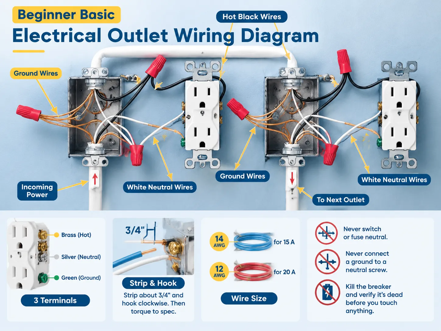
Plugging a standard 120 V plug into an outlet consists of three wires. The hot wire goes to a brass or dark plug terminal; the neutral wire goes to a silver plug terminal; and the ground wire goes to a green plug terminal. The proper way to put the wires on a terminal is to strip off approximately 3⁄4 inch of the insulation and then wrap the wire loosely around the terminal in a clockwise direction before tightening the screw so that the hook will be on the inside when you tighten the screw. If your circuit works with 15 A of current, you have to use a 14 AWG wire. If your circuit draws 20 A or more, you must use a 12 AWG wire. Never open or blow the neutral terminals; never add ground wires to neutral terminals; and always make sure that the circuit is down before working with the wires.
What an Outlet Is Made Of
First, get to know the terminologies associated with different components in an installation.
- Receptacle refers to the component fixed to the wall when installed. The term “outlet” is however broader, as it refers to any area where power is taken from.
- Face is the flat portion of the receptacle having slots. A single duplex receptacle has 2 sets of slots.
- The terminal screws are silver, brass and green screws on different sections of the receptacle.
- Push-in holes are tiny holes at the back of the component which makes it possible to insert wires without the necessity of wrapping them; however, this makes the connection weak.
- Mounting strap is the metallic component used to fix the receptacle securely to the wall.
Slots are used to denote the various types of reception of power. In 15 A North American receptacles, the shorter slot is the hot slot, longer slot is the neutral, and the grounding hole is round. If you are ever unsure which is which, the difference between 2-prong and 3-prong outlets covers what each configuration can and cannot do — and why a two-slot receptacle is a grounding question rather than just an age question.
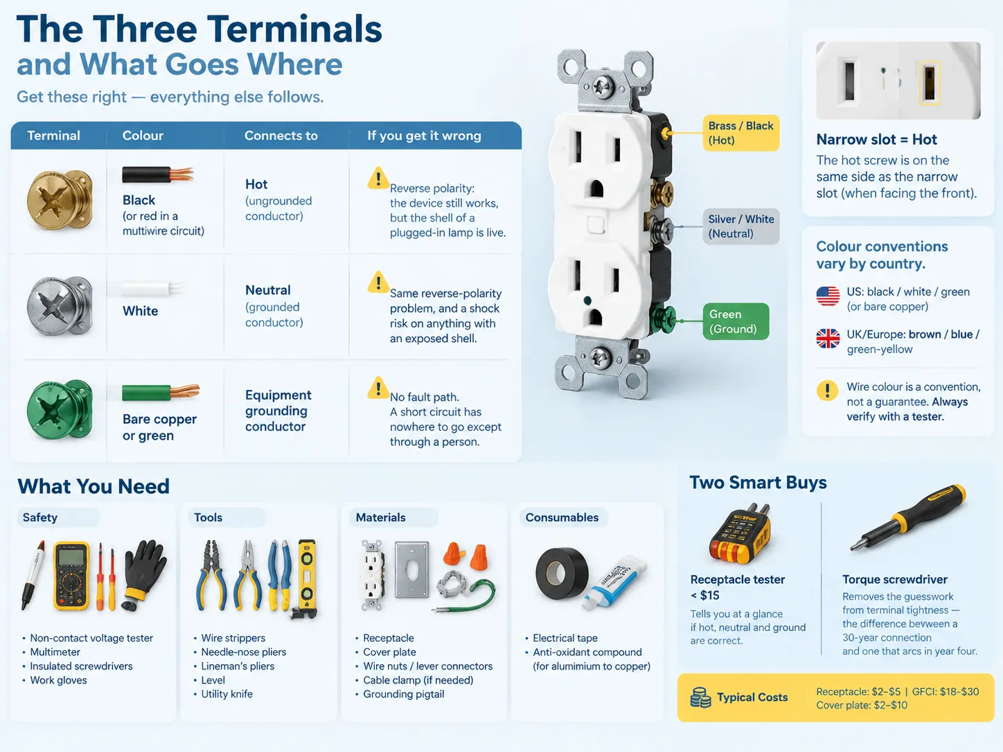
The Three Terminals, and What Goes Where
This is the part to memorise. Everything else follows from it.
| Terminal | Colour | Connects to | What happens if you get it wrong |
|---|---|---|---|
| Brass or dark screw | Black (or red in a multiwire circuit) | Hot — the ungrounded conductor | Reverse polarity: the device still works, but the shell of a plugged-in lamp is live |
| Silver screw | White | Neutral — the grounded conductor | Same reverse-polarity problem, and a shock risk on anything with an exposed shell |
| Green screw | Bare copper or green | Equipment grounding conductor | No fault path. A short circuit has nowhere to go except through a person |
Three memory aids that have left their mark on the human mind: brass for hot; silver means neutral; green represents ground. If the color of the screw is not clear due to the old and cheap device, then look at the slot, narrow slot for electric current, with that screw being in the same part of the device facing you.
Color codes depends on the country and the time of installation. In the UK and Europe, brown color is used for the live wire, blue for the neutral wire, and yellow/green for the earth wire. This is why imported appliances can cause a lot of problems.If you are working on anything you did not install yourself, treat colour as a hint and verify with a tester. How the different conventions map onto each other is set out in this explanation of what electrical wire colours mean.
What You Need Before You Start
| Category | Items |
|---|---|
| Safety | Non-contact voltage tester, multimeter, insulated screwdrivers, work gloves |
| Tools | Wire strippers (with the right gauge stops), needle-nose pliers, lineman’s pliers, level, utility knife |
| Materials | Receptacle, cover plate, wire nuts or lever connectors, cable clamp if the box needs one, grounding pigtail |
| Consumables | Electrical tape, anti-oxidant compound if you are joining aluminium to copper devices |
There are two tools to own instead of borrowing. A receptacle tester is inexpensive, less than $15, and will show you immediately if the hot, neutral and ground connections are fine, which is the most frequent error you can make. A torque screwdriver enables you to avoid random guessing about the tightness of connections, which makes the difference between 30 years of a connection life or having it arc within four years.
The budget is limited. The cost of the standard duplex receptacle is between $2 and $5, while a tamper-resistant one may be bought for $3 to $8, a GFCI receptacle is sold for $18 to $30, and cover plates vary from $2 to $10. The job may be done at the cost of almost just your time.
The Three Layouts You Will Meet
You will definitely find an outlet wiring diagram that fits one of these categories. It is very important to determine your category before starting any work.
- At the end of the loop. Only one cable is connected with a wire from the black wire to brass screw, white wire to silver screw, and green wire to the ground.
- In the center of the loop. Here you have two cables connecting. The incoming hot cable is joined with the outgoing hot cable, and incoming neutral connects with outgoing neutral cable. In this case, both grounds connect together and there are short pieces connecting the outlet with the cable.
- Controllable outlet. One part of the outlet is controlled by a switch; thus, the bridge wire was removed and one part of the outlet receives electricity continuously while another receives electricity on/off.This is the layout people get wrong most often, and it is worth reading the specific walkthrough of wiring a switched outlet before you break that tab — once broken, it cannot be restored.
Before taking out the old device, make sure to take a picture of it. It is easy to keep four screws and three wires in mind until you are holding a phone in one hand and a screwdriver in the other.
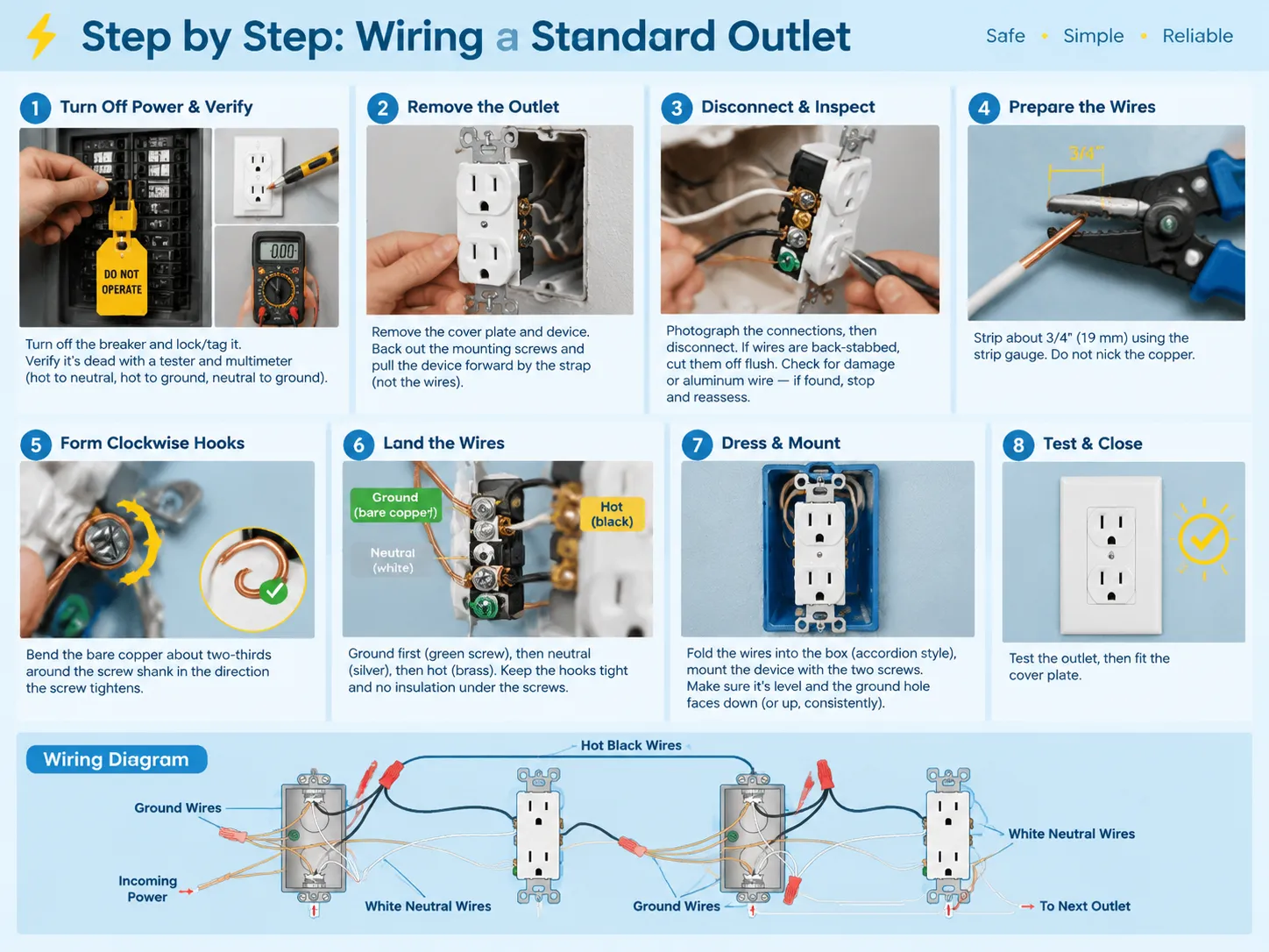
Step by Step: Wiring a Standard Outlet
- Before you begin working on the circuit, turn off the power supply at the breaker and lock or leave a tag on it if any other person is in the house.
- Once you activate the power supply again, you need to be sure that there is no voltage in the circuit at the receptacle by using a non-contact voltage tester and eventually confirming it with the help of multimeter, measuring hot to neutral, hot to ground and neutral to ground. All those measurements must be zero. Remember that electric shock from a turned off switch does not mean that the circuit is dead. A breaker labelled “light” might not be applicable only in terms of electrical connection of lighting fixtures.
- Take away the cover plate and pulling the device, do not pull it in a careless manner.
- Photograph the whole scheme of connections and then disconnect them, unhooking a wire from each terminal.
- Inspect the conductors. Be on the lookout for cuts, burns, or badly oxidized wires. If you find any defects, just assess the condition of the wire more carefully and do not attempt to fix it.
- Strip the ends. The method of stripping is simple: only cut or use the special tool for stripping about three-quarters of an inch of insulation off without damaging the conductor.
- Create a hook on the end. In doing this, the twisting motion must be done in the direction of screwing in the screw. Ensure that the cords are tight and reaching the end of the screw.
- Start from the ground, making sure that the green screw is used for that job first. If the box is metallic, add a connection from the working wire to the metal body of the box.
- Next, attach the neutral to the silver screw and hot to the brass one, ensuring to make no loose ends.
- Tighten the screws according to the instructions of the manufacturer. Making all the screws tight is important to prevent a fire from happening from loose terminals.
- Put the wires in the box, if necessary.
- Put the two screws in, allowing for the box to be leveled as well as the ground wire to fit properly. Do not forget about testing before closing the box.
One point that people forget about: check box fill styles and apply it if you work with new boxes or replace them.
Box Fill: The Rule Beginners Never Hear About
Every electrical box has a capacity and every wire, device, and connector takes away from this capacity. If you overload the box, you could end up with damaged insulation, which would result in a fault that shows up in the months to come.
When following the NEC method (Article 314.16), the amount of space taken by each conductor is added plus other allowances.
| Item | 14 AWG | 12 AWG |
|---|---|---|
| Each hot, neutral or traveler | 2.0 cu in | 2.25 cu in |
| The device (counts as two conductors) | 4.0 cu in | 4.5 cu in |
| All equipment grounds, combined | 2.0 cu in | 2.25 cu in |
| Internal cable clamps, combined | 2.0 cu in | 2.25 cu in |
A typical box that has two cables (14/2) and one device, has a volume of about 4 conductors (2 hot and 2 neutral) at 2.0 and ground at 2.0, and the device at 4.0, giving a total of approximately 14cubic inches of volume. Old Work single gang boxes usually have a volume of 14-18 cubic inches, so you are already approaching the volume limits. However, if you want to add a third cable, a deeper box or double gang box will be required.
It is important to check the volume of the box, usually stenciled on the back, prior to purchasing.
The Safety Rules That Are Not Optional
There are four requirements which govern almost all outlet jobs, and these are the requirements checked by the inspector.
- Grounding. The receptacles used should be of the type which necessitates grounding and should also be grounded (NEC 406.3). One cannot simply connect the ground screw to the neutral if the box does not have a ground conductor because that is an illegal ground and it is dangerous.
- Replacement of an ungrounded receptacle. NEC 406.4(D) lists the options for replacing an ungrounded receptacle including the use of GFCI protection.
- The use of tamper-resistance devices. In dwellings, the receptacles rated for 125 V 15 A and 20 A should be categorized as tamper resistant (NEC 406.12) with minor exceptions such as receptacles that are positioned above 5½ feet from the ground or receptacles used for special appliances.
- GFCI and AFCI protection. If GFCI applies in kitchens, bathrooms, garages, and damp locations, then AFCI applies in most cases for branch circuits of dwellings (NEC 210.8).
This last point seems to confuse a few people especially when they are simply swapping an outlet. If the circuit has not previously been protected using AFCI, the requirements will be adhered. When changing a receptacle in the kitchen or bathroom, ensure that the protection is available already as it will need to be applied subsequently if it hasn’t already been used. The practical difference between the two device types, and where each is required, is explained in this comparison of GFCI and regular outlets.
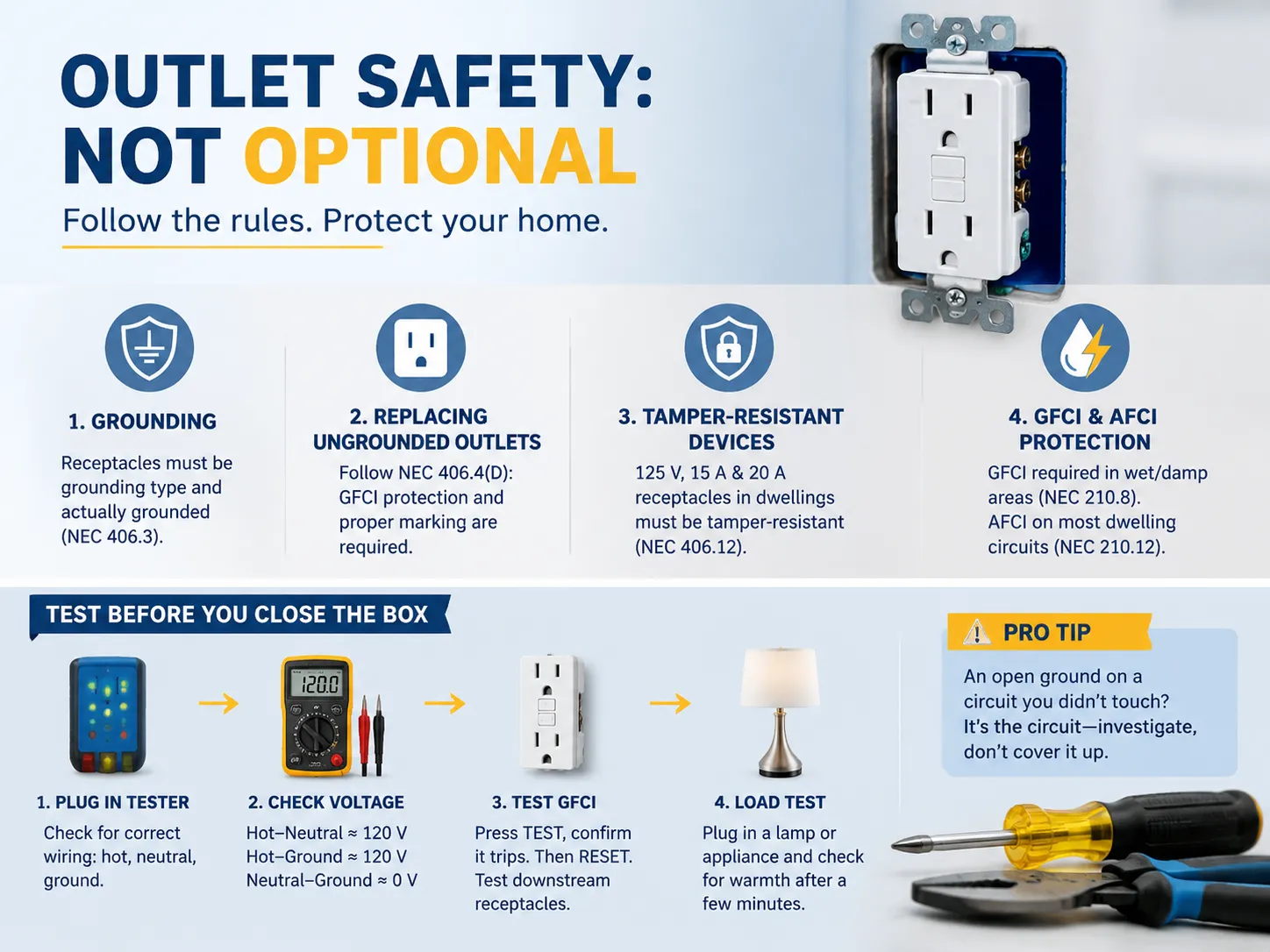
How to Test Before You Close the Box
- Check with the power off. There must be no exposed copper wire at any connectors, no insulation underneath screws, no wires being pinched between fitting and box, and ground should be connected only to green wire.
- Switch on breaker and plug in a receptacle tester. Three lights and a proper pattern indicate that hot, neutral, and ground are where they should be. The tester is the simplest method to detect the reversed polarity, open ground or neutral.
- If you want the real figures, you can check with a multimeter. You should get about 120 V from hot to neutral and from hot to ground and roughly zero V between ground and neutral. Otherwise you will know which conductor is wrong.
- If the device is a GFCI, press the test button, check that it trips and reset it. Make sure to do the same with the downstream receptacles as it confirms that load terminals are wired properly.
- Load test. Plug some piece of load equipment such as a lamp or hairdryer working on minimum load and check for warmth after some minutes. Warmer face means a loose termination.
If your tester indicates that there is an open ground in the circuit you did not work with, it does not concern your wiring but rather indicates the fact that there is something wrong with the circuit and it should be inspected instead of being concealed.
How Many Outlets on a Circuit
There isn’t a hard limit on how many general-purpose outlets can be used on a circuit; however, there is a practical one. The recommendation is for a maximum of about 10 outlets on a 15 A circuit and 13 on a 20 A circuit for general purposes. Kitchens are different; they must have at least two 20 A small appliance circuits, and these circuits cannot power any lights or other equipment.
The spacing of outlets is separately regulated. Under the “2-6-12” rule according to NEC 210.52, there must be an outlet for any lengths of wall that are 2 feet wide or longer; no spot along the floorline should be more than 6 feet away from the outlet, and the furthest distance between outlets along a wall should not exceed 12 feet. Kitchen countertops have stricter distance regulations with no spot farther than 24 inches away from an outlet, which comes to pretty much an outlet every 4 feet.
If you are adding an outlet rather than replacing one, that spacing rule decides where it goes, and a licensed electrician will check it. How much load you can actually put on the circuit is a separate calculation, covered in this look at how many watts an outlet can handle.
Common Beginner Mistakes
| Mistake | What happens | Fix |
|---|---|---|
| Back-stabbing instead of using screws | High-resistance connection, heat, intermittent failure | Use the screw terminals, or a back-wire clamp if the device has one |
| Counter-clockwise hook | Wire squeezes out as you tighten | Re-form the hook clockwise |
| Too much bare copper | Arc to the box or to the adjacent terminal | Strip to the gauge, trim the excess |
| Ground on the neutral screw | Bootleg ground; false sense of safety | Ground goes to green and to the box only |
| Hot and neutral reversed | Works, but the lamp shell is live | Swap to brass = black, silver = white; verify with a tester |
| Using the device as a splice on a 20 A circuit | 15 A device carrying 20 A through its internals | Pigtail the conductors and run one set to the device |
| Overfilled box | Damaged insulation, delayed fault | Larger box, or reduce the conductor count |
| Not torquing the terminals | The most common cause of outlet fires | Use a torque screwdriver to the manufacturer’s figure |
There is one additional point that we should not overlook: working live because it was difficult to turn the power off. Most of the severe electrical injuries in households occur on circuits where the electrician thought there was no mood current. Therefore, test, and test again!
When to Stop and Call Someone
Replacing an outlet is something an experienced beginner can easily accomplish. However, in various cases this will not be possible:
- If a house was built in the late 1960s or early 1970s, there can be Aluminum branch-circuit wiring that is not only complicated but requires special tools for its replacement.
- You may encounter either Knob-and-tube wiring or fabric-insulated wiring, where the insulation breaks off as soon as you move it.
- If there is no ground conductor in the circuit, you will need to deal with more complicated alternatives than just swapping the devices.
- If you can see the signs of burning such as black or melted parts that point out that there are problems related to the circuit rather than the device.
- If the box is too small or not fixed properly, you will need to repair the wall around it.
When you deal with replacing a device rather than adding one, the process becomes very straightforward. However, if it involves running new cables it becomes much more complicated than a simple device replacement.
FAQ
What is the 2 6 12 rule for outlets?
The acronym refers to the NEC 210.52 specification requiring receptacle placement. Walls with a length of 2 feet or more must have a receptacle installed; jacks cannot be placed more than 6 feet apart between each other and therefore can be placed up to a maximum of 12 feet apart along the same wall. This guideline is applicable to livable spaces only.
How to wire a standard electrical outlet?
Switch off the break and check that the circuit is not live. Remove insulation for about 3/4 of an inch and connect the bare copper wire around the screws; connect the ground wire to the green screw, the white wire to the silver screw, and the black wire to the brass screw. Finally, use a receptacle tester to check if the device is working before you attach the cover.
How to do electrical wiring for beginners?
First, start off with the replacements rather than the new circuits. You have to learn the three terminals and their colour convention, and you also need to buy a receptacle tester and a torque screwdriver, and only work on the circuits that you have verified to be dead. First, practice on an end-of-run outlet with a single cable before moving to a middle-of-run box that contains splices. In most places, any work that involves new cable work, panel work, or aluminum wiring has to be carried out by one who is a licensed Electrician.
What is the basic wiring diagram?
The layout for a single outlet at the end of a line requires three wires: black goes from the cable to the brass screw, white goes to the silver screw and bare copper goes to the green screw, with grounding connected to a metal box. For an outlet at the middle of a line, a splice must be done for every colour and there should be a short pigtail connected to the device. Everything else is a variation of these two systems.
References
- NFPA — NFPA 70 National Electrical Code, Articles 210, 314, 406 and 300
- Electrical Safety Foundation International — home electrical safety guidance and fire statistics
- Leviton — receptacle wiring diagrams, terminal identification and torque specifications
- Hubbell — wiring device installation instructions and tamper-resistant product data
- Grainger — receptacle, GFCI and cover plate pricing and specification data
- International Association of Electrical Inspectors — box fill calculation and grounding interpretation
- EC&M Magazine — installation practice guidance on terminations and receptacle replacement
- US Consumer Product Safety Commission — receptacle recall notices and residential electrical hazard data
Conclusion
The schematic for electric wiring usually consists of three terminal points and a typical color coding: black (grounded), white (silver) and green (ground).
These symbols alone are important, but many other things about the wiring create opportunities for you to make mistakes such as: ensuring that power to the circuit is cut off; stripping and prepping the wire correctly; connecting the wire to the terminal with clockwise twists; properly torqueing the wire to the terminal; keeping within the filling limits of box capacity, etc. You should learn to use the end-of-run receptacle when performing this type of wiring so that you understand how it operates properly, too.