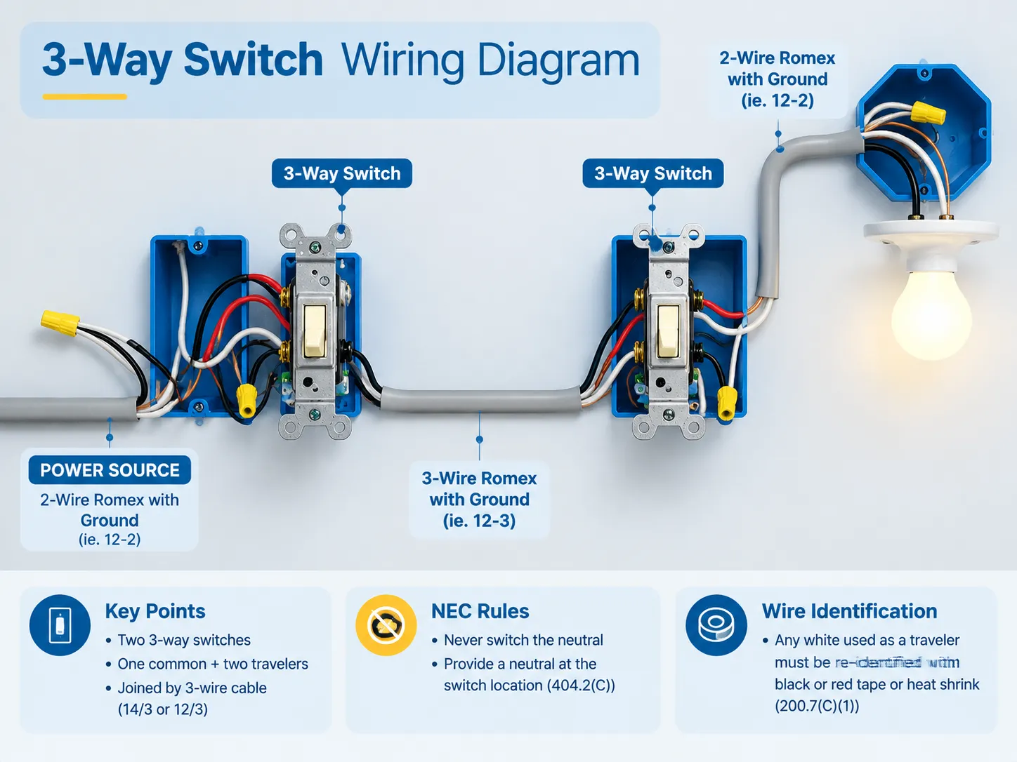
It is only in a standard house wiring system that one can come across the three-way switch circuit where one light bulb is controlled from two different places—and it is also here that most amateur electrical errors are made as three terminals on the 3, way switch look interchangeable while actually one of them is the entrance of electricity.
In short, a three-way lighting circuit requires two three-way switches (each switch consists of a common terminal and two traveler terminals). A three-wire connection (14/3 or 12/3) is used to connect the two switches. The hot cable of the circuit is connected to the common terminal of the first switch and goes through the second switch’s common terminal to reach the light. Its two traveler wires connect the two switches using their brass screws. It is important to mention that NEC rules do not allow the switching of neutral. Instead, you have to ensure that your lighting circuit has neutral if it is located in or between switch boxes (404.2(C)) and that any white conductor that functions as traveler is temporarily flagged in accordance with 200.7(C)(1).
What a 3-Way Switch Actually Is
Remove the name of the circuit and what you have is a single-pole double-throw switch (SPDT). Internally it has one common and two output contacts. What it does is not per se “on” or “off,” as it only provides the path from the incoming line to either one of the two travelers.
This is why the light’s state depends on the combination of switches and not on either of them alone. In any moment there is one traveler live and another one dead so flipping either switch is just changing their places. However, if both travelers are live at the same time or if the common is on the traveler screw, the circuit cannot work.
The device has three terminals and one ground:
- The black screw – dark, bronze, or marked COM. This is the point of entry or exit for the main hot wire;
- Two brass screws – the travelers through which the current flows between the two switches;
- And the green screw only for equipment grounding.
People are often confused by the terminology since a device called 2-way switch in the UK is known as 3-way switch in North America while what North America calls a 4-way switch is the intermediate switch in the UK.If you are working across both conventions, this comparison of the differences between 2-way and 3-way switching is worth reading before you touch a terminal.
What You Need Before You Start
| Item | Detail |
|---|---|
| Two 3-way switches | 15 A or 20 A to match the circuit, standard toggle, rocker or smart |
| Cable between switches | 14/3 for a 15 A circuit, 12/3 for 20 A — the third conductor is what makes the traveler pair possible |
| Feed and switch-leg cable | 14/2 or 12/2 as required |
| Boxes | Deep single-gang (22 cu in or more) or double-gang — a 3-way box carries more conductors than a single-pole box and standard 14–18 cu in boxes are frequently too small |
| Tools | Non-contact voltage tester, multimeter with continuity, wire strippers, lineman’s pliers, screwdrivers, tape or heat shrink for re-identification |
| Consumables | Wire nuts or lever connectors, cable clamps, grounding pigtails |
The expense of the switch is quite affordable; a generic 3-way switch tends to cost only a few bucks and smart 3-way switches are priced between $25 and $75 based upon the communication protocol used. The major expense comes from incorrectly installation which will incur the fee of electric contract who has to come for help.
Reading the Wires in the Box
Colour isn’t a rule, it’s a convention, and this is where we run into problems.
- Black — typically the ungrounded (hot) conductor and the switched leg to the fixture.
- Red — the second traveler in a 14/3 or 12/3 cable; red and black being used in all events as the traveler pair.
- White — the grounded (neutral) conductor but, in older switch-loop wiring, it was sometimes used as either a hot or a traveler conductor.
- Bare copper or green — the equipment grounding conductor.
According to NEC 200.7(C)(1), if a white conductor is utilized as an ungrounded conductor, it shall be permanently re-identified in a color other than white, gray or green at every termination or point of visibility. The requirement will be fulfilled if black or red electrical tape is wrapped around it or heat shrink tubing slid over it, painting of the conductor is allowed, but not recommended. The typical failure is the case when taping is executed at the level of the switch but nothing is done for the conductor above the ceiling canopy. Colour conventions and what they do and don’t guarantee are covered in this look at what electrical wire colours actually mean.
One differentiation is more important than all the colors at hand. A neutral wire in a switch box is a white wire grouped together with the other white cables at the back of the box and is detached from the switch. A white wire connected to a switch terminal cannot be referred to as a neutral wire — it is other type of wire that is white in color.
Schematic One: Power Enters at the First Switch
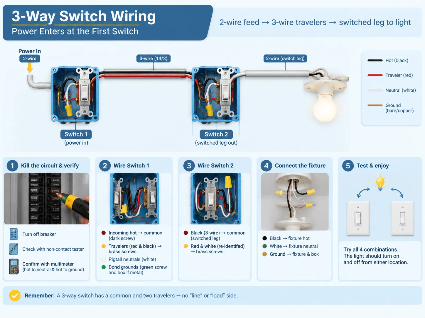
This layout is the most commonly seen, therefore it is usually the first layout everyone learns. Power enters through 2-wire cable, and travelers travel to the second switch via 3-wire cable whereas the switched leg leaves the second switch to the light.
- As before, cutting the power, in addition to verifying it is necessary. First, flip the breaker, then use a non-contact tester at the box and check it with multimeter between neutral and hot, as well as hot and ground wires.
- From Switch 1 find out the incoming hot wire cable arriving via a 2-wire supply, and attach it to common (dark) screw.
- Then the 3-wire travelers should be connected. The red and black wires of 14/3 supply will go to both brass screws. This does not matter which traveler is attached to which screw; they should just be consistent with one another.
- Next, connect the neutrals or pigtail them. White wires coming to and from the fixture must be connected by a wire connector or a wire nut. This connection must be made at Switch location according to NEC 404.2 (C).
- Bond the grounds. Connect all grounding conductors together, and add a pigtail to connect it to the green screw and to the box.
- At Switch 2, attach the black wire of the 3-wire to the screws. Black wire acts as a switched wire that is coming back to the fixture.
- Connect red and re-identified white wire or red and black wires, if any.
- Be sure to connect the switched leg to the fixture afterwards.
- Close everything up and test the circuit using a regular procedure.
If your experience was limited to installation of single pole switches, the most difficult thing to unlearn will be distinction between “line side” and “load side”. With 3-way switches there are no such sides – only common and travelers. The mechanics of a one-terminal-in, one-terminal-out device are set out in this guide to wiring a single-pole switch, and the contrast is what makes the 3-way click.
Schematic Two: Power at the Fixture (Switch Loop)
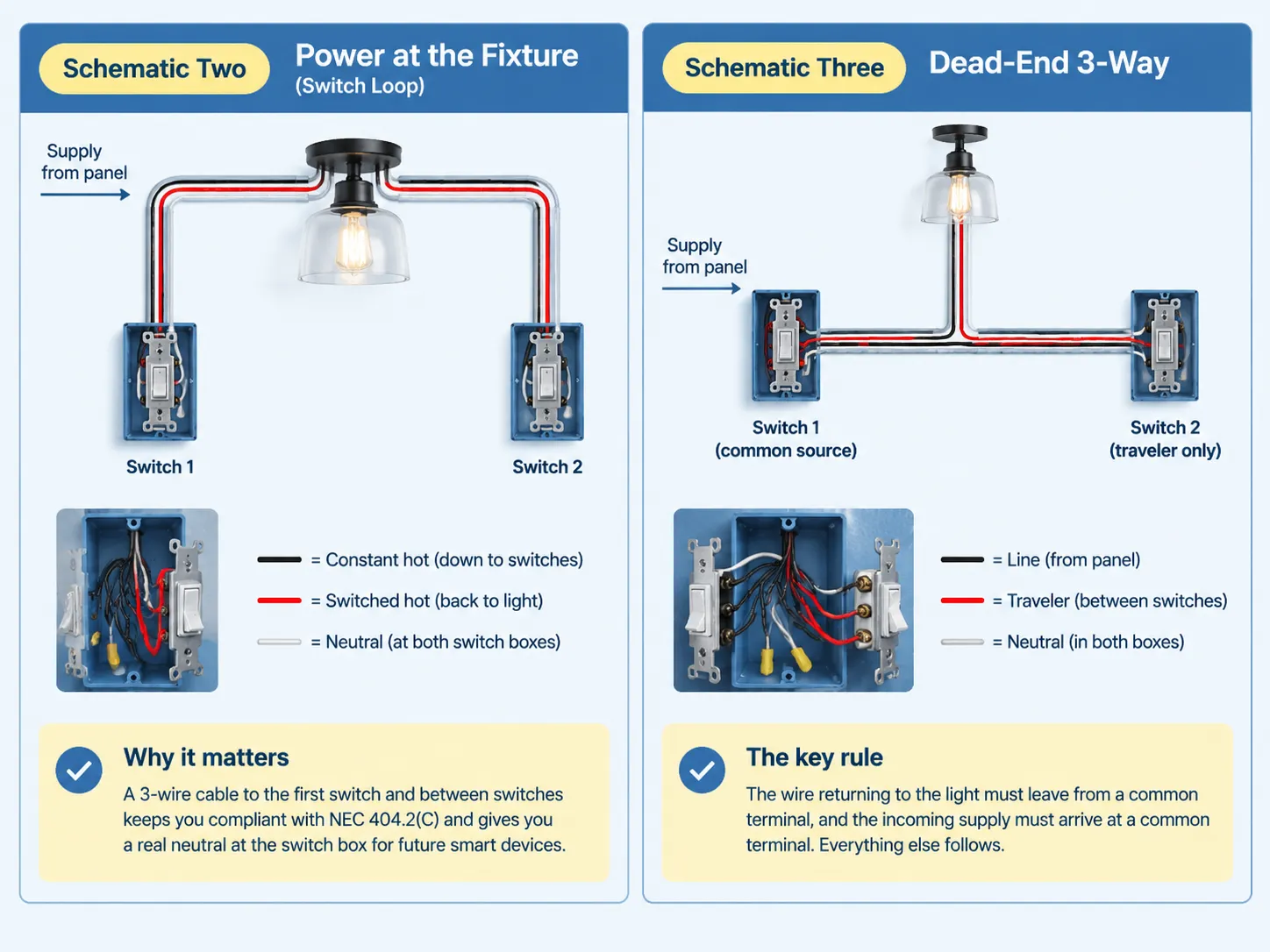
In this case, the electricity enters via the fixture. There was a time when the switch loop consisted of two wires with one of them being a hot wire. Since this method was used for a long time, it is still very common in older homes. However, that practice is now outdated.
In accordance with NEC 404.2(C), you must install a 3-wire conductor from your fixture to the first switch and connect your two switches through another 3-wire cable. The black wire will provide a constant power supply at the switches, while the red wire will supply the switched power back to the fixture through the second traveler wire. The third wire makes it possible to have a neutral wire at both locations.
Adopting this rather complicated technique involves using only one wire and eliminating potential future complications. The use of the neutral wire at the switch allows you to install a smart switch, a timer, or any other device without breaking through the wall.
Schematic Three: Dead-End 3-Way
In the dead-end configuration, both the power supply and the switch leg start from the same box, which causes one of the two switch boxes to receive only the traveler wire. This is when the usefulness of labeling during rough-in becomes evident since the box has three wires and no obvious reference point.
The immutable rule remains the same: outgoing conductor returns to the light from a common terminal and incoming supply arrives at a common terminal. The rest will follow.
Going Beyond Two Locations: Where the 4-Way Fits
When utilizing three or more control points, 4-way switches must be utilized. The wiring arrangement remains constant, with a 3-way switch located at both ends and with one or more 4-way switches in between them. The wires coming from the first 3-way switch connect to one terminal pair of the 4-way switch while the other terminal pair is connected to the next switch. 4-way switches do not have a common terminal; it simply connects the traveler wires.
In this context, it is important to know that you can put a 4-way switch anywhere in the middle of your former wiring layout but not at either end. If that means that you cannot use that location, it might be worthwhile for you to use a wireless light switch instead.
NEC Rules That Actually Shape the Wiring
- In subsection 404.2(A), it highlights that you must only switch the hot wire; all three-way and four-way operations must be carried in the ungrounded conductor. This eliminates the antiquated Carter method where the travelers used both hot and neutral cords and the light fixture was able to remain in a powered condition even when the light was off. If your tests reveal a switch that connects a fixture straight to the neutral wire, then the resolving option is to re-wire the circuit.
- Subsection 404.2(C) states that you must have neutral wire present at the location of the switch. This requirement was established on the 2011 edition states that you need to have the system with a grounded conductor at the switch boxes responsible for lighting of bathrooms, hallways, staircase and habitable premises. If there are many spots controlling one light and the entire floor area is visible from those locations, then a single area will suffice. An exception for that rule are raceway installations or any boxes that can be used without removal of finishing materials.
- Subsection 200.7(C)(1) states that you must re-identify white wire being used as hot. It is necessary to make permanent marking in the color other than white, grey or green at the terminals. In case of usage of switch loops with re-identified white wire it is possible to power it and switch power on or off.
- Subsection 314 states that in case of box filling you need to include all wire carrying current and add one for all the grounds and one for internal clamps and two for the device itself. For 14 AWG cable size you will need to have 2.0 not less cubic inches for every wire. If you require a switch with 14/2 line-in, 14/3 line-out and 14/2 feed this will mean that the initial box must contain about 20 cubic inches that is bigger than standard single-gang old-work box can provide.
The edition of the National Electrical Code 2026 has stated that all the regulations concerning dimmer switches and electronic control switches have been moved to new Part III of Article 406 from Sections 406.30 up to 406.40. The new edition does not introduce anything new but only moves the requirement from one edition to another whereas the applicability of the corresponding edition depends on the implementation by local authorities.
Where the Code Comes From: What the Fire Data Says
The analysis based on NFPA which was posted in February, 2022. Thus, it estimated that home fire incidents rose to the average number of 32,620 in the US fire departments from 2015 to 2019 concerning electrical distribution and devices for lighting. The majority of cases were attributed to the wiring system including some construction components, such as switches, sockets and the wiring of a circuit which is considered to be responsible for 68% of the cases, while the heat in 73% of fires starting due to such events was due to arcing.
The most frequent causes of arcing are loose wire connections and mistaken identification of the wires. Both are under your full control during your assignment at a 3-way job.
Testing Before You Close the Box
To check the status of the neutral and to make sure the common is the correct one.
- The first check is to find the common using a multimeter. While the power is off and the conductors are disconnected, turn the meter to the continuity setting. Place one probe on the common screw and the other probe on the brass screw. Turn the switch on, and the meter will beep on one switch position and be silent on the second one. Do the same with the second brass screw. The screw that shows continuity is the common.
- The second check is to check that there is a neutral. With the power on, measure the voltage from the white wire to ground. The neutral wire will not show any voltage. If the voltage is around 120V, you are putting voltage through a hot wire that is switched, and it is not wired in accordance with the colors.
Do not use trial and error through toggling switches and watching the bulb. Trial and error switches cause arcing and degradation of components and do not tell you anything about the wiring and identify the dangerous mistakes.
Troubleshooting Table
| Symptom | Most likely cause | What to check |
|---|---|---|
| Light works only when the other switch is in one position | Common conductor and a traveler are swapped at one switch | Move the conductor that belongs on COM back to the dark screw |
| One switch controls the light, the other does nothing | Both travelers under one brass screw, or a failed switch | Confirm each brass screw holds exactly one traveler, then test the switch |
| Neither switch turns the light on | Tripped breaker, failed lamp, open splice or traveler, no power at COM | Lamp and breaker first, then inspect splices and terminals with the power off |
| Breaker trips when a switch is flipped | Traveler or switched conductor touching neutral or ground, or damaged insulation | Leave the breaker off and inspect every connection before resetting |
| Flicker, buzz, or a warm switch face | Loose screw or push-in connection, overload, dimmer mismatched to the load | Re-torque to spec, move push-in conductors to screw terminals, check ratings |
| LEDs glow faintly when the circuit is off | An illuminated locator switch leaking a small current through the LED driver | Swap to a non-illuminated 3-way switch or fit a bypass component at the fixture |
If the wiring does not match any diagram known, or if the circuit breaker keeps tripping, you must stop adjusting the wires and call a qualified electrician to determine the fault in the circuitry. The process of trial and error on an energized circuit is dangerous to one’s health and life.
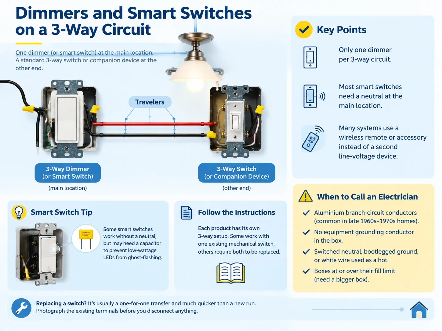
Dimmers and Smart Switches on a 3-Way Circuit
You can use a dimmer on a 3-way circuit but can’t use two dimmers on a single 3-way circuit. The usual combination involves using a dimmer on one end of the 3-way circuit and using a standard 3-way switch or compatible companion device on the other end.The working combinations are explained in this guide to dimmer switch three-way compatibility, and they are worth checking before you buy, because a mismatched pair simply will not function.
Smart switches operate on the same principles with one added complication. The majority of them require a neutral in the switch box and the wiring described in code 404.2(C)(1) has to be used. A few of them can in fact function without a neutral, in which case a special device has to be connected on the load to prevent low-current LED from flickering. Some other systems can do without a second switch if an accessory wireless switch is being used instead of the line-voltage one.
Follow the wiring instructions attached to the device rather than trying to do this according to standard wiring diagrams, as the systems are different.
When to Call an Electrician
The process itself is pretty simple and legally permitted for homeowners in most jurisdictions in the United States, but there are some scenarios that should deter you from doing the work:
- Aluminum branch circuit conductors, which require a different method of termination and were usually present in homes built in the late 1960s through early 1970s.
- A circuit that has no grounding conductor whatsoever and therefore cannot have a new switch connected to the box without rewiring.
- Any signs of a switched neutral, a bootleg ground, or a white conductor used as a hot without any identification.
- Any boxes that are already at or over fill capacity, where the correct answer is a bigger box and not forcing more things in.
If you are replacing the switch rather than building the circuit from scratch, the job is a one-for-one transfer and much shorter than a new run — the process is covered in this guide to replacing a light switch. Photograph the existing terminals before you disconnect anything, and the new wiring becomes a reference rather than a puzzle.
FAQ
How do I properly wire a 3-way switch?
Connect the hot wire to the common (dark) terminal on the first switch, connect the red and black traveler wires from the brass terminal on the first switch to the brass terminal on the second switch, and connect to the output leg to the light from the common terminal of the second switch. Connect all neutral wires by pigtailing them together so that they don’t connect to either terminal and connect together all ground points to ground the system. Finally make sure to check the common using the continuity meter before closing the junction box.
What happens if a 3-way switch is wired wrong?
There are generally four situations: the light is only turned on from one switch; one of the switches does nothing; the light doesn’t turn on at all; or the circuit breaker trips once the switch is turned on. The most dangerous is a switched neutral, in which the light looks like it is working, but the circuit is still live even when the switch is turned off. The most common mistake is swapping the common and one of the travelers around.
Does it matter where the wires go on a 3-way switch?
The input is where it is different for one terminal and the same for the rest. The live wire has to be connected to the common terminal of the first switch and the switched wire has to come out from the common terminal of the second switch. The travelers can go in either of the terminals, as long as they are used for both ends. One of the errors is the wrong input and the other is swapping the travelers.
Do 3-way switches need neutrals?
While the switch may not be responsible for this, the box certainly is. As per NEC 404.2(C), the use of dedicated grounded conductors is mandated at switch locations that are responsible for controlling the lighting in bathrooms, hallways, stairways and in spaces with people. This requirement was introduced in the 2011 edition of the NEC due to the fact that electronic controls, timers and occupancy sensors need continuous references. Therefore, the practice requires the running of 14/3 or 12/3 throughout both switch locations even for the case of plain mechanical switches.
References
- NFPA — NFPA 70 National Electrical Code, Articles 200, 314, 404 and 406
- NFPA — home fire involvement of electrical distribution and lighting equipment, February 2022 analysis
- US Consumer Product Safety Commission — residential electrical safety guidance and recall information
- International Association of Electrical Inspectors — analysis of the 2026 NEC changes moving snap switch rules to Article 406 Part III
- EC&M Magazine — box fill calculation guidance and code interpretation resources for installers
- Leviton — 3-way and multi-location switch wiring diagrams and device ratings
- Lutron — multi-location dimmer and smart switch compatibility documentation
- Electrical Safety Foundation International — home electrical safety and arc fault statistics
Conclusion
A three-way circuit is formed of three circuits located at the proper places, which include the hot circuit to common, common wire to the light, and adjustable travelers linked to the two brass screws. The rest of the wiring procedure ensures that it has been done properly, that a real neutral has been placed in the box, that the grounds have been bonded, that all the white wires have been correctly identified as they carry hot current, and that the box has sufficient volume to accommodate the fixture without squeezing. It is essential to check the common with a meter before the box has been closed.