لا يمكن العثور على دائرة مفتاح ثلاثي الاتجاهات حيث يتم التحكم في مصباح واحد من مكانين مختلفين إلا في نظام الأسلاك المنزلية القياسي — وهنا أيضًا تحدث معظم الأخطاء الكهربائية للهواة حيث تبدو الأطراف الثلاثة في المفتاح ثلاثي الاتجاهات قابلة للتبادل بينما في الواقع أحدها هو مدخل الكهرباء.
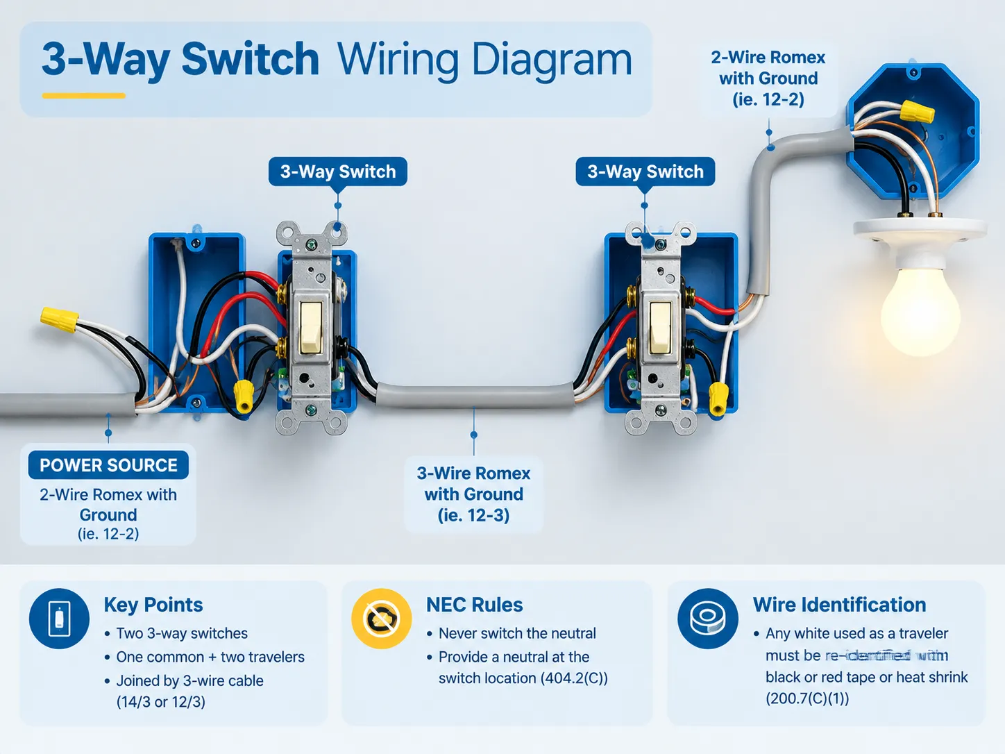
باختصار، تتطلب دائرة إضاءة ثلاثية الاتجاه مفتاحين ثلاثيي الاتجاه (كل مفتاح يتكون من طرف مشترك وطرفين مسافرين). يتم استخدام توصيل بثلاثة أسلاك (14/3 أو 12/3) لربط المفتاحين. يتم توصيل الكابل الحار للدائرة بالطرف المشترك للمفتاح الأول ويمر عبر الطرف المشترك للمفتاح الثاني ليصل إلى المصباح. توصل أسلاك المسافرين الاثنين المفتاحين باستخدام براغي النحاس الخاصة بهما. من المهم ذكر أن قواعد NEC لا تسمح بتبديل السلك المحايد. بدلاً من ذلك، يجب التأكد من أن دائرة الإضاءة تحتوي على سلك محايد إذا كانت موجودة داخل أو بين صناديق المفاتيح (404.2(C)) وأن أي موصل أبيض يعمل كمسافر يتم تمييزه مؤقتًا وفقًا لـ 200.7(C)(1).
ما هو المفتاح ثلاثي الاتجاهات فعليًا
إذا أزلت اسم الدائرة، فستحصل على مفتاح أحادي القطب مزدوج الإرسال (SPDT). داخليًا يحتوي على طرف مشترك وطرفين خرج. ما يفعله ليس بالضرورة “تشغيل” أو “إيقاف”، بل يوفر فقط المسار من الخط الوارد إلى أحد طرفي المسافرين.
لهذا السبب تعتمد حالة المصباح على تركيبة المفاتيح وليس على أي منها بمفرده. في أي لحظة يكون أحد المسافرين نشطًا والآخر غير نشط، لذا فإن قلب أي مفتاح هو مجرد تبديل أماكنهما. ومع ذلك، إذا كان كلا المسافرين نشطين في نفس الوقت أو إذا كان الطرف المشترك متصلًا بمسمار المسافر، فلن تعمل الدائرة.
يحتوي الجهاز على ثلاثة أطراف وأرضي واحد:
- المسمار الأسود – داكن، برونزي، أو موسوم بـ COM. هذا هو نقطة دخول أو خروج السلك الحار الرئيسي؛;
- مسماران من النحاس – هما المسافران اللذان يتدفق التيار بين المفتاحين من خلالهما؛;
- والمسمار الأخضر مخصص فقط لتأريض المعدات.
غالبًا ما يختلط على الناس المصطلحات حيث يُعرف الجهاز المسمى مفتاح ذو اتجاهين في المملكة المتحدة بالمفتاح ثلاثي الاتجاهات في أمريكا الشمالية، بينما ما تسميه أمريكا الشمالية مفتاحًا رباعي الاتجاه هو المفتاح الوسيط في المملكة المتحدة. إذا كنت تعمل عبر كلا النظامين، فإن هذا المقارنة بين الفروقات بين التبديل ذو الاتجاهين والثلاثي الاتجاهات تستحق القراءة قبل لمس أي طرف.
ما تحتاجه قبل البدء
| البند | التفاصيل |
|---|---|
| مفتاحان ثلاثيا الاتجاه | 15 أمبير أو 20 أمبير لتتناسب مع الدائرة، مفتاح تقليدي، روكَر أو ذكي |
| كابل بين المفتاحين | 14/3 لدائرة 15 أمبير، 12/3 لدائرة 20 أمبير — الموصل الثالث هو ما يجعل زوج المسافرين ممكنًا |
| كابل التغذية وكابل الساق التبديلية | 14/2 أو 12/2 حسب الحاجة |
| الصناديق | صندوق عميق ذو فتحة واحدة (22 بوصة مكعبة أو أكثر) أو صندوق ذو فتحتين — صندوق ثلاثي الاتجاه يحمل موصلات أكثر من صندوق أحادي القطب وغالبًا ما تكون صناديق 14-18 بوصة مكعبة القياسية صغيرة جدًا |
| الأدوات | جهاز اختبار الجهد بدون تماس، مقياس متعدد مع اختبار الاستمرارية، قواطع الأسلاك، كماشة الفني الكهربائي، مفكات، شريط لاصق أو أنابيب انكماش حراري لإعادة التعريف |
| المستهلكات | وصلات الأسلاك أو موصلات الرافعة، مشابك الكابلات، أسلاك التأريض |
تكلفة المفتاح معقولة جدًا؛ عادةً ما يكلف مفتاح 3-طريق عام بضعة دولارات فقط، وتُسعر مفاتيح 3-طريق الذكية بين $25 و$75 بناءً على بروتوكول الاتصال المستخدم. النفقات الرئيسية تأتي من التركيب غير الصحيح الذي يستلزم استدعاء مقاول كهربائي للمساعدة.
قراءة الأسلاك في الصندوق
اللون ليس قاعدة، بل هو اتفاقية، وهنا تكمن المشكلة.
- الأسود — عادةً الموصل غير المؤرض (الحار) والقدم المتحكم به إلى الجهاز.
- الأحمر — الناقل الثاني في كابل 14/3 أو 12/3؛ الأحمر والأسود يُستخدمان دائمًا كزوج الناقلين.
- الأبيض — الموصل المؤرض (الحيادي) ولكن في الأسلاك القديمة لدائرة المفتاح، كان يُستخدم أحيانًا كموصل حار أو ناقل.
- النحاس العاري أو الأخضر — موصل تأريض المعدات.
وفقًا لـ NEC 200.7(C)(1)، إذا تم استخدام موصل أبيض كموصل غير مؤرض، يجب إعادة تعريفه بشكل دائم بلون غير الأبيض أو الرمادي أو الأخضر عند كل نقطة إنهاء أو نقطة رؤية. يتم الوفاء بهذا الشرط إذا تم لف شريط كهربائي أسود أو أحمر حوله أو وضع أنبوب انكماش حراري عليه، يُسمح بطلاء الموصل لكنه غير مستحب. الفشل النموذجي يحدث عندما يتم لف الشريط عند مستوى المفتاح فقط ولا يُفعل شيء للموصل فوق سقف الغطاء. الاتفاقيات اللونية وما تضمنه أو لا تضمنه مغطاة في هذا العرض ما تعنيه ألوان الأسلاك الكهربائية فعليًا.
تمييز واحد أهم من كل الألوان المتاحة. السلك الحيادي في صندوق المفتاح هو سلك أبيض مجمع مع الأسلاك البيضاء الأخرى في خلف الصندوق ومنفصل عن المفتاح. السلك الأبيض المتصل بطرف المفتاح لا يمكن اعتباره سلك حيادي — إنه نوع آخر من الأسلاك البيضاء اللون.
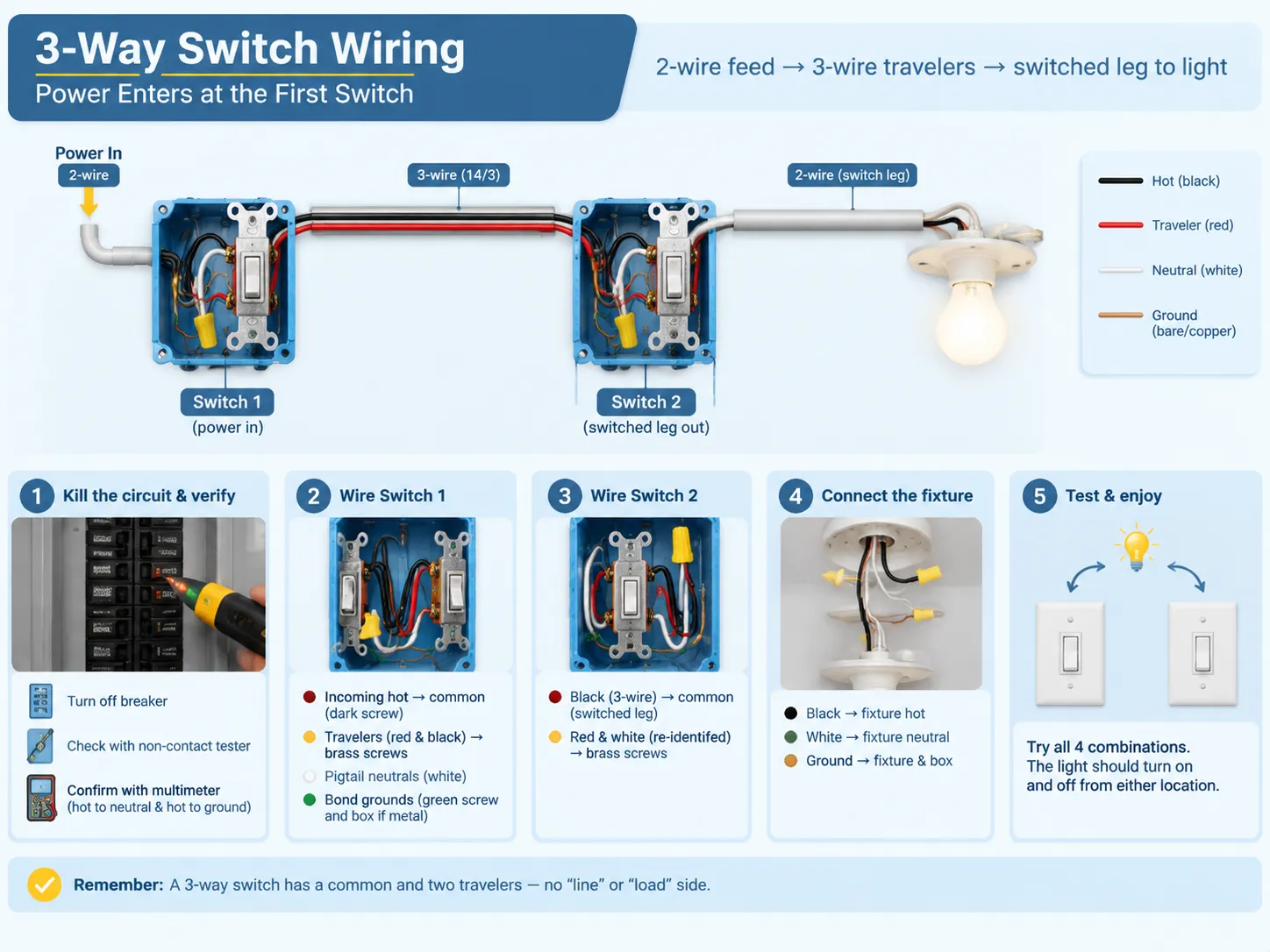
المخطط الأول: دخول الطاقة عند المفتاح الأول
هذا الترتيب هو الأكثر شيوعًا، لذلك عادةً ما يكون أول ترتيب يتعلمه الجميع. تدخل الطاقة عبر كابل ذو سلكين، والناقلون ينتقلون إلى المفتاح الثاني عبر كابل ذو 3 أسلاك بينما القدم المتحكم به يخرج من المفتاح الثاني إلى الضوء.
- كما في السابق، يجب قطع الطاقة بالإضافة إلى التحقق من ذلك. أولاً، قم بقلب القاطع، ثم استخدم جهاز اختبار بدون تماس عند الصندوق وافحصه بمقياس متعدد بين الحيادي والحار، وكذلك بين الحار والأسلاك الأرضية.
- من المفتاح 1، حدد سلك الحار الوارد عبر كابل تزويد ذو سلكين، وقم بتوصيله بالبرغي المشترك (الداكن).
- ثم يجب توصيل الناقلين ذوي الثلاثة أسلاك. ستذهب الأسلاك الحمراء والسوداء من تزويد 14/3 إلى كلا البرغيين النحاسيين. لا يهم أي ناقل متصل بأي برغي؛ يجب فقط أن يكونا متسقين مع بعضهما البعض.
- بعد ذلك، قم بتوصيل الأسلاك المحايدة أو ربطها بسلك ذيل. يجب توصيل الأسلاك البيضاء القادمة من وترجع إلى الجهاز بواسطة موصل أسلاك أو صمولة أسلاك. يجب إجراء هذا الاتصال في موقع المفتاح وفقًا لـ NEC 404.2 (C).
- اربط الأسلاك الأرضية. قم بتوصيل جميع موصلات التأريض معًا، وأضف سلك ذيل لتوصيله بالبرغي الأخضر وبالصندوق.
- عند المفتاح 2، قم بتوصيل السلك الأسود من الأسلاك الثلاثة بالبراغي. يعمل السلك الأسود كسلك متحكم يعود إلى الجهاز.
- قم بتوصيل السلك الأحمر والسلك الأبيض المعاد تعريفه أو الأسلاك الحمراء والسوداء، إذا وجدت.
- تأكد من توصيل السلك المتحكم به بالجهاز بعد ذلك.
- أغلق كل شيء وقم باختبار الدائرة باستخدام الإجراء العادي.
إذا كانت خبرتك محدودة في تركيب مفاتيح القطب الواحد، فإن أصعب شيء ستحتاج إلى نسيانه هو التمييز بين “جانب الخط” و“جانب الحمل”. مع مفاتيح الثلاثة اتجاهات لا توجد مثل هذه الجوانب – فقط المشترك والأسلاك المتنقلة. تم توضيح آلية جهاز ذو طرف دخول وطرف خروج في هذا الدليل لـ توصيل مفتاح قطب واحد, ، والتباين هو ما يجعل مفتاح الثلاثة اتجاهات يعمل.
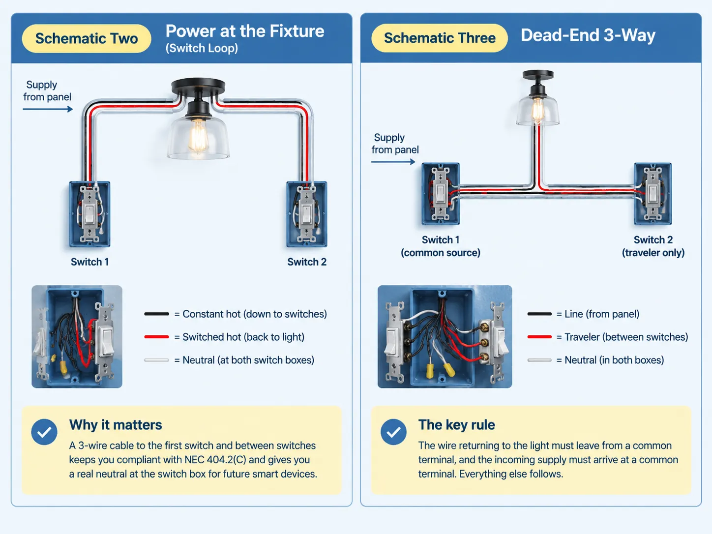
Schematic Two: Power at the Fixture (Switch Loop)
In this case, the electricity enters via the fixture. There was a time when the switch loop consisted of two wires with one of them being a hot wire. Since this method was used for a long time, it is still very common in older homes. However, that practice is now outdated.
In accordance with NEC 404.2(C), you must install a 3-wire conductor from your fixture to the first switch and connect your two switches through another 3-wire cable. The black wire will provide a constant power supply at the switches, while the red wire will supply the switched power back to the fixture through the second traveler wire. The third wire makes it possible to have a neutral wire at both locations.
Adopting this rather complicated technique involves using only one wire and eliminating potential future complications. The use of the neutral wire at the switch allows you to install a smart switch, a timer, or any other device without breaking through the wall.
Schematic Three: Dead-End 3-Way
In the dead-end configuration, both the power supply and the switch leg start from the same box, which causes one of the two switch boxes to receive only the traveler wire. This is when the usefulness of labeling during rough-in becomes evident since the box has three wires and no obvious reference point.
The immutable rule remains the same: outgoing conductor returns to the light from a common terminal and incoming supply arrives at a common terminal. The rest will follow.
Going Beyond Two Locations: Where the 4-Way Fits
When utilizing three or more control points, 4-way switches must be utilized. The wiring arrangement remains constant, with a 3-way switch located at both ends and with one or more 4-way switches in between them. The wires coming from the first 3-way switch connect to one terminal pair of the 4-way switch while the other terminal pair is connected to the next switch. 4-way switches do not have a common terminal; it simply connects the traveler wires.
In this context, it is important to know that you can put a 4-way switch anywhere in the middle of your former wiring layout but not at either end. If that means that you cannot use that location, it might be worthwhile for you to use a wireless light switch instead.
NEC Rules That Actually Shape the Wiring
- In subsection 404.2(A), it highlights that you must only switch the hot wire; all three-way and four-way operations must be carried in the ungrounded conductor. This eliminates the antiquated Carter method where the travelers used both hot and neutral cords and the light fixture was able to remain in a powered condition even when the light was off. If your tests reveal a switch that connects a fixture straight to the neutral wire, then the resolving option is to re-wire the circuit.
- Subsection 404.2(C) states that you must have neutral wire present at the location of the switch. This requirement was established on the 2011 edition states that you need to have the system with a grounded conductor at the switch boxes responsible for lighting of bathrooms, hallways, staircase and habitable premises. If there are many spots controlling one light and the entire floor area is visible from those locations, then a single area will suffice. An exception for that rule are raceway installations or any boxes that can be used without removal of finishing materials.
- Subsection 200.7(C)(1) states that you must re-identify white wire being used as hot. It is necessary to make permanent marking in the color other than white, grey or green at the terminals. In case of usage of switch loops with re-identified white wire it is possible to power it and switch power on or off.
- Subsection 314 states that in case of box filling you need to include all wire carrying current and add one for all the grounds and one for internal clamps and two for the device itself. For 14 AWG cable size you will need to have 2.0 not less cubic inches for every wire. If you require a switch with 14/2 line-in, 14/3 line-out and 14/2 feed this will mean that the initial box must contain about 20 cubic inches that is bigger than standard single-gang old-work box can provide.
The edition of the National Electrical Code 2026 has stated that all the regulations concerning dimmer switches and electronic control switches have been moved to new Part III of Article 406 from Sections 406.30 up to 406.40. The new edition does not introduce anything new but only moves the requirement from one edition to another whereas the applicability of the corresponding edition depends on the implementation by local authorities.
Where the Code Comes From: What the Fire Data Says
The analysis based on NFPA which was posted in February, 2022. Thus, it estimated that home fire incidents rose to the average number of 32,620 in the US fire departments from 2015 to 2019 concerning electrical distribution and devices for lighting. The majority of cases were attributed to the wiring system including some construction components, such as switches, sockets and the wiring of a circuit which is considered to be responsible for 68% of the cases, while the heat in 73% of fires starting due to such events was due to arcing.
The most frequent causes of arcing are loose wire connections and mistaken identification of the wires. Both are under your full control during your assignment at a 3-way job.
Testing Before You Close the Box
To check the status of the neutral and to make sure the common is the correct one.
- The first check is to find the common using a multimeter. While the power is off and the conductors are disconnected, turn the meter to the continuity setting. Place one probe on the common screw and the other probe on the brass screw. Turn the switch on, and the meter will beep on one switch position and be silent on the second one. Do the same with the second brass screw. The screw that shows continuity is the common.
- The second check is to check that there is a neutral. With the power on, measure the voltage from the white wire to ground. The neutral wire will not show any voltage. If the voltage is around 120V, you are putting voltage through a hot wire that is switched, and it is not wired in accordance with the colors.
Do not use trial and error through toggling switches and watching the bulb. Trial and error switches cause arcing and degradation of components and do not tell you anything about the wiring and identify the dangerous mistakes.
Troubleshooting Table
| العرض | Most likely cause | ما الذي يجب التحقق منه |
|---|---|---|
| Light works only when the other switch is in one position | Common conductor and a traveler are swapped at one switch | Move the conductor that belongs on COM back to the dark screw |
| One switch controls the light, the other does nothing | Both travelers under one brass screw, or a failed switch | Confirm each brass screw holds exactly one traveler, then test the switch |
| Neither switch turns the light on | Tripped breaker, failed lamp, open splice or traveler, no power at COM | Lamp and breaker first, then inspect splices and terminals with the power off |
| Breaker trips when a switch is flipped | Traveler or switched conductor touching neutral or ground, or damaged insulation | Leave the breaker off and inspect every connection before resetting |
| Flicker, buzz, or a warm switch face | Loose screw or push-in connection, overload, dimmer mismatched to the load | Re-torque to spec, move push-in conductors to screw terminals, check ratings |
| LEDs glow faintly when the circuit is off | An illuminated locator switch leaking a small current through the LED driver | Swap to a non-illuminated 3-way switch or fit a bypass component at the fixture |
If the wiring does not match any diagram known, or if the circuit breaker keeps tripping, you must stop adjusting the wires and call a qualified electrician to determine the fault in the circuitry. The process of trial and error on an energized circuit is dangerous to one’s health and life.
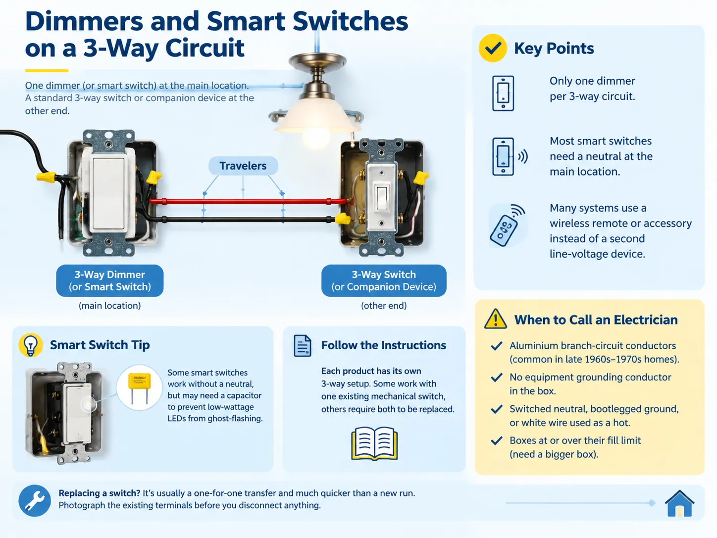
Dimmers and Smart Switches on a 3-Way Circuit
You can use a dimmer on a 3-way circuit but can’t use two dimmers on a single 3-way circuit. The usual combination involves using a dimmer on one end of the 3-way circuit and using a standard 3-way switch or compatible companion device on the other end.The working combinations are explained in this guide to dimmer switch three-way compatibility, and they are worth checking before you buy, because a mismatched pair simply will not function.
Smart switches operate on the same principles with one added complication. The majority of them require a neutral in the switch box and the wiring described in code 404.2(C)(1) has to be used. A few of them can in fact function without a neutral, in which case a special device has to be connected on the load to prevent low-current LED from flickering. Some other systems can do without a second switch if an accessory wireless switch is being used instead of the line-voltage one.
Follow the wiring instructions attached to the device rather than trying to do this according to standard wiring diagrams, as the systems are different.
متى تتصل بفني كهربائي
The process itself is pretty simple and legally permitted for homeowners in most jurisdictions in the United States, but there are some scenarios that should deter you from doing the work:
- Aluminum branch circuit conductors, which require a different method of termination and were usually present in homes built in the late 1960s through early 1970s.
- A circuit that has no grounding conductor whatsoever and therefore cannot have a new switch connected to the box without rewiring.
- Any signs of a switched neutral, a bootleg ground, or a white conductor used as a hot without any identification.
- Any boxes that are already at or over fill capacity, where the correct answer is a bigger box and not forcing more things in.
If you are replacing the switch rather than building the circuit from scratch, the job is a one-for-one transfer and much shorter than a new run — the process is covered in this guide to ودليل. Photograph the existing terminals before you disconnect anything, and the new wiring becomes a reference rather than a puzzle.
الأسئلة المتكررة
How do I properly wire a 3-way switch?
Connect the hot wire to the common (dark) terminal on the first switch, connect the red and black traveler wires from the brass terminal on the first switch to the brass terminal on the second switch, and connect to the output leg to the light from the common terminal of the second switch. Connect all neutral wires by pigtailing them together so that they don’t connect to either terminal and connect together all ground points to ground the system. Finally make sure to check the common using the continuity meter before closing the junction box.
What happens if a 3-way switch is wired wrong?
There are generally four situations: the light is only turned on from one switch; one of the switches does nothing; the light doesn’t turn on at all; or the circuit breaker trips once the switch is turned on. The most dangerous is a switched neutral, in which the light looks like it is working, but the circuit is still live even when the switch is turned off. The most common mistake is swapping the common and one of the travelers around.
Does it matter where the wires go on a 3-way switch?
The input is where it is different for one terminal and the same for the rest. The live wire has to be connected to the common terminal of the first switch and the switched wire has to come out from the common terminal of the second switch. The travelers can go in either of the terminals, as long as they are used for both ends. One of the errors is the wrong input and the other is swapping the travelers.
Do 3-way switches need neutrals?
While the switch may not be responsible for this, the box certainly is. As per NEC 404.2(C), the use of dedicated grounded conductors is mandated at switch locations that are responsible for controlling the lighting in bathrooms, hallways, stairways and in spaces with people. This requirement was introduced in the 2011 edition of the NEC due to the fact that electronic controls, timers and occupancy sensors need continuous references. Therefore, the practice requires the running of 14/3 or 12/3 throughout both switch locations even for the case of plain mechanical switches.
المراجع
- NFPA — NFPA 70 National Electrical Code, Articles 200, 314, 404 and 406
- NFPA — home fire involvement of electrical distribution and lighting equipment, February 2022 analysis
- US Consumer Product Safety Commission — residential electrical safety guidance and recall information
- International Association of Electrical Inspectors — analysis of the 2026 NEC changes moving snap switch rules to Article 406 Part III
- EC&M Magazine — box fill calculation guidance and code interpretation resources for installers
- Leviton — 3-way and multi-location switch wiring diagrams and device ratings
- Lutron — multi-location dimmer and smart switch compatibility documentation
- Electrical Safety Foundation International — home electrical safety and arc fault statistics
الخاتمة
A three-way circuit is formed of three circuits located at the proper places, which include the hot circuit to common, common wire to the light, and adjustable travelers linked to the two brass screws. The rest of the wiring procedure ensures that it has been done properly, that a real neutral has been placed in the box, that the grounds have been bonded, that all the white wires have been correctly identified as they carry hot current, and that the box has sufficient volume to accommodate the fixture without squeezing. It is essential to check the common with a meter before the box has been closed.