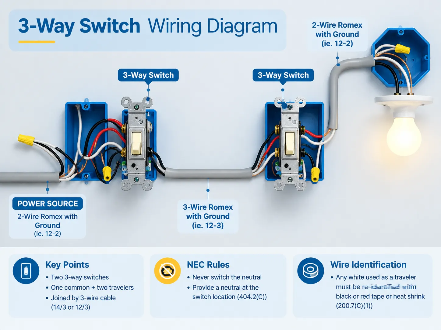
É somente em um sistema padrão de fiação residencial que se pode encontrar o circuito de interruptor three-way onde uma lâmpada é controlada de dois lugares diferentes—e é também aqui que a maioria dos erros elétricos amadores ocorre, pois três terminais no interruptor 3-way parecem intercambiáveis enquanto na verdade um deles é a entrada da eletricidade.
Em resumo, um circuito de iluminação three-way requer dois interruptores three-way (cada interruptor consiste em um terminal comum e dois terminais viajantes). Uma conexão de três fios (14/3 ou 12/3) é usada para conectar os dois interruptores. O cabo quente do circuito é conectado ao terminal comum do primeiro interruptor e passa pelo terminal comum do segundo interruptor para alcançar a luz. Seus dois fios viajantes conectam os dois interruptores usando seus parafusos de latão. É importante mencionar que as regras do NEC não permitem a comutação do neutro. Em vez disso, você deve garantir que seu circuito de iluminação tenha neutro se estiver localizado dentro ou entre caixas de interruptores (404.2(C)) e que qualquer condutor branco que funcione como viajante seja temporariamente sinalizado de acordo com 200.7(C)(1).
O que um Interruptor 3-Way Realmente É
Remova o nome do circuito e o que você tem é um interruptor single-pole double-throw (SPDT). Internamente ele tem um comum e dois contatos de saída. O que ele faz não é propriamente “ligar” ou “desligar,” pois ele apenas fornece o caminho da linha de entrada para um dos dois viajantes.
É por isso que o estado da luz depende da combinação dos interruptores e não de nenhum deles sozinho. Em qualquer momento há um viajante energizado e outro desenergizado, então acionar qualquer um dos interruptores é apenas trocar seus lugares. No entanto, se ambos os viajantes estiverem energizados ao mesmo tempo ou se o comum estiver no parafuso do viajante, o circuito não pode funcionar.
O dispositivo tem três terminais e um terra:
- O parafuso preto – escuro, bronze ou marcado COM. Este é o ponto de entrada ou saída para o fio quente principal;
- Dois parafusos de latão – os viajantes pelos quais a corrente flui entre os dois interruptores;
- E o parafuso verde apenas para aterramento do equipamento.
As pessoas frequentemente ficam confusas com a terminologia, pois um dispositivo chamado 2-way switch no Reino Unido é conhecido como 3-way switch na América do Norte, enquanto o que a América do Norte chama de 4-way switch é o interruptor intermediário no Reino Unido. Se você estiver trabalhando com ambas as convenções, esta comparação das diferenças entre comutação 2-way e 3-way vale a pena ler antes de tocar em um terminal.
O Que Você Precisa Antes de Começar
| Item | Detalhes |
|---|---|
| Dois interruptores 3-way | 15 A ou 20 A para corresponder ao circuito, toggle padrão, rocker ou smart |
| Cabo entre interruptores | 14/3 para um circuito de 15 A, 12/3 para 20 A — o terceiro condutor é o que torna possível o par viajante |
| Cabo de alimentação e cabo de perna de comutação | 14/2 ou 12/2 conforme necessário |
| Caixas | Caixa profunda single-gang (22 cu in ou mais) ou double-gang — uma caixa 3-way carrega mais condutores do que uma caixa single-pole e caixas padrão de 14–18 cu in frequentemente são muito pequenas |
| Ferramentas | Testador de voltagem sem contato, multímetro com continuidade, decapadores de fios, alicates de eletricista, chaves de fenda, fita ou tubo termo retrátil para reidentificação |
| Consumíveis | Conectores de fio ou conectores de alavanca, braçadeiras de cabo, ramais de aterramento |
O custo do interruptor é bastante acessível; um interruptor 3-way genérico tende a custar apenas alguns dólares e interruptores 3-way inteligentes são precificados entre $25 e $75 com base no protocolo de comunicação utilizado. A maior despesa vem da instalação incorreta, que acarretará a taxa do contrato elétrico que terá que vir para ajudar.
Lendo os Fios na Caixa
A cor não é uma regra, é uma convenção, e é aqui que encontramos problemas.
- Preto — tipicamente o condutor não aterrado (fase) e o fio comutado para a luminária.
- Vermelho — o segundo viajante em um cabo 14/3 ou 12/3; vermelho e preto são usados em todos os casos como o par de viajantes.
- Branco — o condutor aterrado (neutro), mas, em fiação antiga de loop de interruptor, às vezes era usado como condutor fase ou viajante.
- Cobre nu ou verde — o condutor de aterramento do equipamento.
De acordo com NEC 200.7(C)(1), se um condutor branco for utilizado como condutor não aterrado, ele deve ser permanentemente reidentificado com uma cor diferente de branco, cinza ou verde em cada terminação ou ponto visível. O requisito será cumprido se uma fita elétrica preta ou vermelha for enrolada ao redor dele ou se um tubo termo retrátil for colocado sobre ele; pintar o condutor é permitido, mas não recomendado. A falha típica ocorre quando a fita é aplicada no nível do interruptor, mas nada é feito para o condutor acima do forro do teto. Convenções de cores e o que elas garantem ou não são abordadas nesta análise de o que as cores dos fios elétricos realmente significam.
Uma diferenciação é mais importante do que todas as cores disponíveis. Um fio neutro em uma caixa de interruptor é um fio branco agrupado com os outros cabos brancos na parte de trás da caixa e está desconectado do interruptor. Um fio branco conectado a um terminal do interruptor não pode ser referido como fio neutro — é outro tipo de fio que é branco.
Esquema Um: A Energia Entra no Primeiro Interruptor
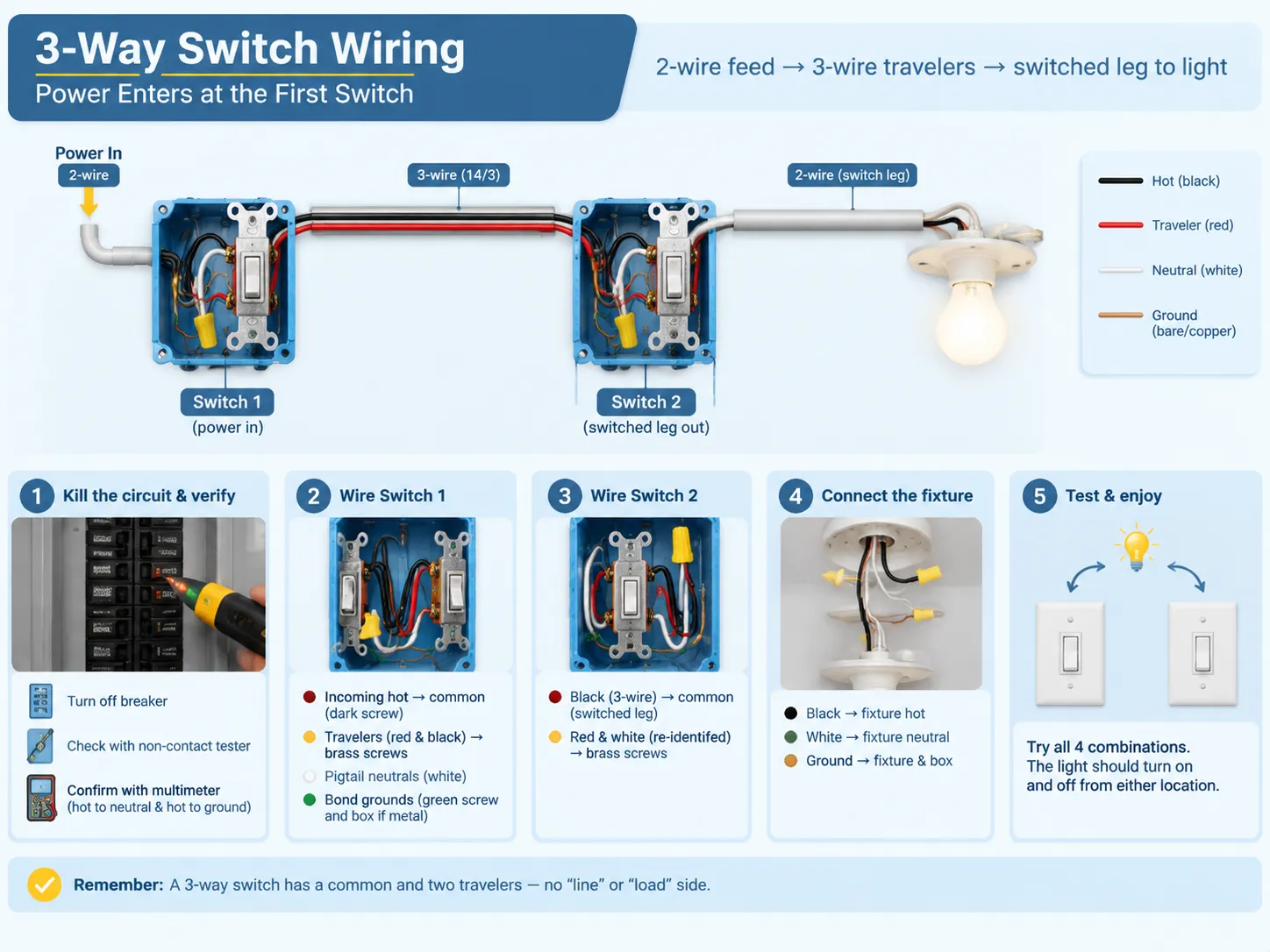
Este layout é o mais comumente visto, portanto geralmente é o primeiro layout que todos aprendem. A energia entra através de cabo de 2 fios, e os viajantes seguem para o segundo interruptor via cabo de 3 fios, enquanto o fio comutado sai do segundo interruptor para a luminária.
- Como antes, desligar a energia, além de verificar, é necessário. Primeiro, desligue o disjuntor, depois use um testador sem contato na caixa e verifique com multímetro entre neutro e fase, assim como entre fase e terra.
- No Interruptor 1, identifique o cabo do fio fase de entrada que chega via alimentação de 2 fios e conecte-o ao parafuso comum (escuro).
- Então os viajantes de 3 fios devem ser conectados. Os fios vermelho e preto da alimentação 14/3 irão para ambos os parafusos de latão. Não importa qual viajante é conectado a qual parafuso; eles apenas devem ser consistentes entre si.
- Em seguida, conecte os neutros ou faça um pigtail com eles. Os fios brancos que chegam e saem da luminária devem ser conectados por um conector de fio ou por uma porca de fio. Essa conexão deve ser feita no local do Interruptor conforme NEC 404.2 (C).
- Faça a ligação dos aterramentos. Conecte todos os condutores de aterramento juntos e adicione um pigtail para conectá-lo ao parafuso verde e à caixa.
- No Interruptor 2, conecte o fio preto do cabo de 3 fios aos parafusos. O fio preto atua como um fio comutado que retorna para a luminária.
- Conecte o fio vermelho e o fio branco reidentificado ou os fios vermelho e preto, se houver.
- Certifique-se de conectar a perna comutada à luminária posteriormente.
- Feche tudo e teste o circuito usando o procedimento padrão.
Se sua experiência foi limitada à instalação de interruptores unipolares, a coisa mais difícil de desaprender será a distinção entre “lado da linha” e “lado da carga”. Com interruptores de 3 vias não existem esses lados – apenas comum e viajantes. A mecânica de um dispositivo com um terminal de entrada e um terminal de saída está descrita neste guia para fiação de um interruptor unipolar, e o contraste é o que faz o interruptor de 3 vias funcionar.
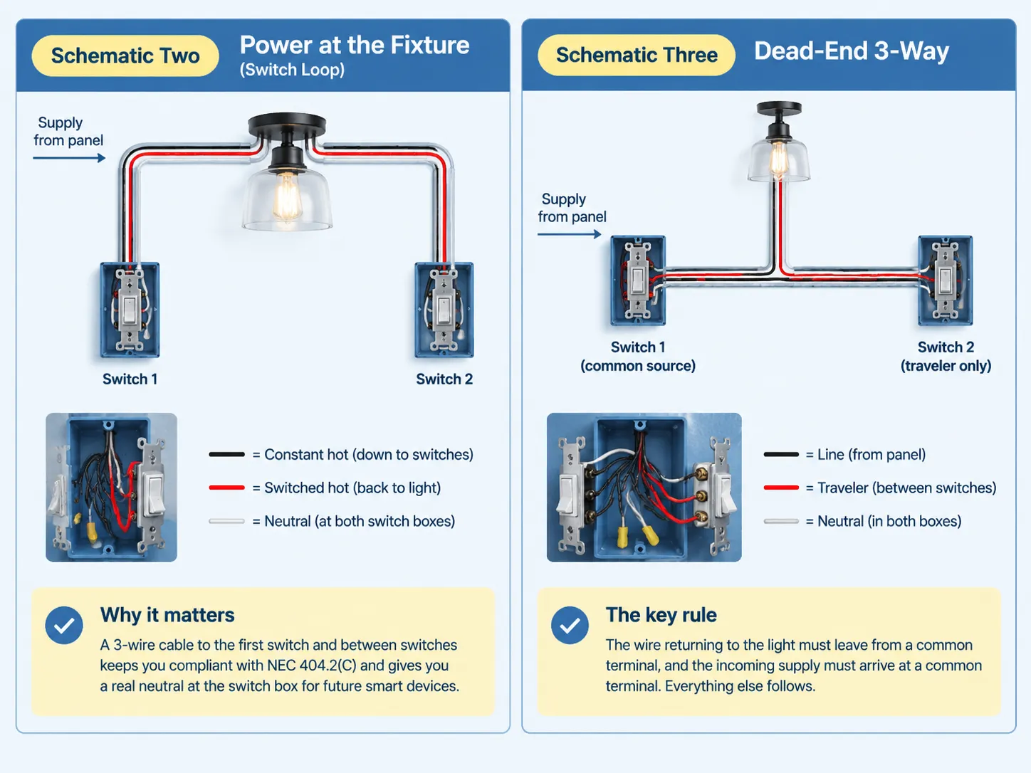
Schematic Two: Power at the Fixture (Switch Loop)
In this case, the electricity enters via the fixture. There was a time when the switch loop consisted of two wires with one of them being a hot wire. Since this method was used for a long time, it is still very common in older homes. However, that practice is now outdated.
In accordance with NEC 404.2(C), you must install a 3-wire conductor from your fixture to the first switch and connect your two switches through another 3-wire cable. The black wire will provide a constant power supply at the switches, while the red wire will supply the switched power back to the fixture through the second traveler wire. The third wire makes it possible to have a neutral wire at both locations.
Adopting this rather complicated technique involves using only one wire and eliminating potential future complications. The use of the neutral wire at the switch allows you to install a smart switch, a timer, or any other device without breaking through the wall.
Schematic Three: Dead-End 3-Way
In the dead-end configuration, both the power supply and the switch leg start from the same box, which causes one of the two switch boxes to receive only the traveler wire. This is when the usefulness of labeling during rough-in becomes evident since the box has three wires and no obvious reference point.
The immutable rule remains the same: outgoing conductor returns to the light from a common terminal and incoming supply arrives at a common terminal. The rest will follow.
Going Beyond Two Locations: Where the 4-Way Fits
When utilizing three or more control points, 4-way switches must be utilized. The wiring arrangement remains constant, with a 3-way switch located at both ends and with one or more 4-way switches in between them. The wires coming from the first 3-way switch connect to one terminal pair of the 4-way switch while the other terminal pair is connected to the next switch. 4-way switches do not have a common terminal; it simply connects the traveler wires.
In this context, it is important to know that you can put a 4-way switch anywhere in the middle of your former wiring layout but not at either end. If that means that you cannot use that location, it might be worthwhile for you to use a wireless light switch instead.
NEC Rules That Actually Shape the Wiring
- In subsection 404.2(A), it highlights that you must only switch the hot wire; all three-way and four-way operations must be carried in the ungrounded conductor. This eliminates the antiquated Carter method where the travelers used both hot and neutral cords and the light fixture was able to remain in a powered condition even when the light was off. If your tests reveal a switch that connects a fixture straight to the neutral wire, then the resolving option is to re-wire the circuit.
- Subsection 404.2(C) states that you must have neutral wire present at the location of the switch. This requirement was established on the 2011 edition states that you need to have the system with a grounded conductor at the switch boxes responsible for lighting of bathrooms, hallways, staircase and habitable premises. If there are many spots controlling one light and the entire floor area is visible from those locations, then a single area will suffice. An exception for that rule are raceway installations or any boxes that can be used without removal of finishing materials.
- Subsection 200.7(C)(1) states that you must re-identify white wire being used as hot. It is necessary to make permanent marking in the color other than white, grey or green at the terminals. In case of usage of switch loops with re-identified white wire it is possible to power it and switch power on or off.
- Subsection 314 states that in case of box filling you need to include all wire carrying current and add one for all the grounds and one for internal clamps and two for the device itself. For 14 AWG cable size you will need to have 2.0 not less cubic inches for every wire. If you require a switch with 14/2 line-in, 14/3 line-out and 14/2 feed this will mean that the initial box must contain about 20 cubic inches that is bigger than standard single-gang old-work box can provide.
The edition of the National Electrical Code 2026 has stated that all the regulations concerning dimmer switches and electronic control switches have been moved to new Part III of Article 406 from Sections 406.30 up to 406.40. The new edition does not introduce anything new but only moves the requirement from one edition to another whereas the applicability of the corresponding edition depends on the implementation by local authorities.
Where the Code Comes From: What the Fire Data Says
The analysis based on NFPA which was posted in February, 2022. Thus, it estimated that home fire incidents rose to the average number of 32,620 in the US fire departments from 2015 to 2019 concerning electrical distribution and devices for lighting. The majority of cases were attributed to the wiring system including some construction components, such as switches, sockets and the wiring of a circuit which is considered to be responsible for 68% of the cases, while the heat in 73% of fires starting due to such events was due to arcing.
The most frequent causes of arcing are loose wire connections and mistaken identification of the wires. Both are under your full control during your assignment at a 3-way job.
Testing Before You Close the Box
To check the status of the neutral and to make sure the common is the correct one.
- The first check is to find the common using a multimeter. While the power is off and the conductors are disconnected, turn the meter to the continuity setting. Place one probe on the common screw and the other probe on the brass screw. Turn the switch on, and the meter will beep on one switch position and be silent on the second one. Do the same with the second brass screw. The screw that shows continuity is the common.
- The second check is to check that there is a neutral. With the power on, measure the voltage from the white wire to ground. The neutral wire will not show any voltage. If the voltage is around 120V, you are putting voltage through a hot wire that is switched, and it is not wired in accordance with the colors.
Do not use trial and error through toggling switches and watching the bulb. Trial and error switches cause arcing and degradation of components and do not tell you anything about the wiring and identify the dangerous mistakes.
Troubleshooting Table
| Sintoma | Most likely cause | O que verificar |
|---|---|---|
| Light works only when the other switch is in one position | Common conductor and a traveler are swapped at one switch | Move the conductor that belongs on COM back to the dark screw |
| One switch controls the light, the other does nothing | Both travelers under one brass screw, or a failed switch | Confirm each brass screw holds exactly one traveler, then test the switch |
| Neither switch turns the light on | Tripped breaker, failed lamp, open splice or traveler, no power at COM | Lamp and breaker first, then inspect splices and terminals with the power off |
| Breaker trips when a switch is flipped | Traveler or switched conductor touching neutral or ground, or damaged insulation | Leave the breaker off and inspect every connection before resetting |
| Flicker, buzz, or a warm switch face | Loose screw or push-in connection, overload, dimmer mismatched to the load | Re-torque to spec, move push-in conductors to screw terminals, check ratings |
| LEDs glow faintly when the circuit is off | An illuminated locator switch leaking a small current through the LED driver | Swap to a non-illuminated 3-way switch or fit a bypass component at the fixture |
If the wiring does not match any diagram known, or if the circuit breaker keeps tripping, you must stop adjusting the wires and call a qualified electrician to determine the fault in the circuitry. The process of trial and error on an energized circuit is dangerous to one’s health and life.
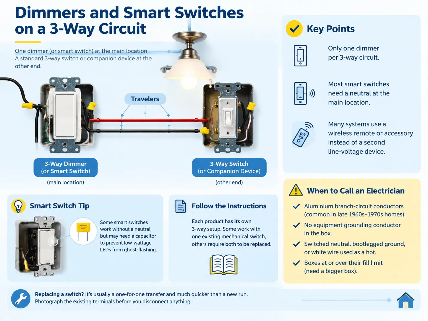
Dimmers and Smart Switches on a 3-Way Circuit
You can use a dimmer on a 3-way circuit but can’t use two dimmers on a single 3-way circuit. The usual combination involves using a dimmer on one end of the 3-way circuit and using a standard 3-way switch or compatible companion device on the other end.The working combinations are explained in this guide to dimmer switch three-way compatibility, and they are worth checking before you buy, because a mismatched pair simply will not function.
Smart switches operate on the same principles with one added complication. The majority of them require a neutral in the switch box and the wiring described in code 404.2(C)(1) has to be used. A few of them can in fact function without a neutral, in which case a special device has to be connected on the load to prevent low-current LED from flickering. Some other systems can do without a second switch if an accessory wireless switch is being used instead of the line-voltage one.
Follow the wiring instructions attached to the device rather than trying to do this according to standard wiring diagrams, as the systems are different.
Quando chamar um eletricista
The process itself is pretty simple and legally permitted for homeowners in most jurisdictions in the United States, but there are some scenarios that should deter you from doing the work:
- Aluminum branch circuit conductors, which require a different method of termination and were usually present in homes built in the late 1960s through early 1970s.
- A circuit that has no grounding conductor whatsoever and therefore cannot have a new switch connected to the box without rewiring.
- Any signs of a switched neutral, a bootleg ground, or a white conductor used as a hot without any identification.
- Any boxes that are already at or over fill capacity, where the correct answer is a bigger box and not forcing more things in.
If you are replacing the switch rather than building the circuit from scratch, the job is a one-for-one transfer and much shorter than a new run — the process is covered in this guide to substituir um interruptor de luz. Photograph the existing terminals before you disconnect anything, and the new wiring becomes a reference rather than a puzzle.
Perguntas Frequentes
How do I properly wire a 3-way switch?
Connect the hot wire to the common (dark) terminal on the first switch, connect the red and black traveler wires from the brass terminal on the first switch to the brass terminal on the second switch, and connect to the output leg to the light from the common terminal of the second switch. Connect all neutral wires by pigtailing them together so that they don’t connect to either terminal and connect together all ground points to ground the system. Finally make sure to check the common using the continuity meter before closing the junction box.
What happens if a 3-way switch is wired wrong?
There are generally four situations: the light is only turned on from one switch; one of the switches does nothing; the light doesn’t turn on at all; or the circuit breaker trips once the switch is turned on. The most dangerous is a switched neutral, in which the light looks like it is working, but the circuit is still live even when the switch is turned off. The most common mistake is swapping the common and one of the travelers around.
Does it matter where the wires go on a 3-way switch?
The input is where it is different for one terminal and the same for the rest. The live wire has to be connected to the common terminal of the first switch and the switched wire has to come out from the common terminal of the second switch. The travelers can go in either of the terminals, as long as they are used for both ends. One of the errors is the wrong input and the other is swapping the travelers.
Do 3-way switches need neutrals?
While the switch may not be responsible for this, the box certainly is. As per NEC 404.2(C), the use of dedicated grounded conductors is mandated at switch locations that are responsible for controlling the lighting in bathrooms, hallways, stairways and in spaces with people. This requirement was introduced in the 2011 edition of the NEC due to the fact that electronic controls, timers and occupancy sensors need continuous references. Therefore, the practice requires the running of 14/3 or 12/3 throughout both switch locations even for the case of plain mechanical switches.
Referências
- NFPA — NFPA 70 National Electrical Code, Articles 200, 314, 404 and 406
- NFPA — home fire involvement of electrical distribution and lighting equipment, February 2022 analysis
- US Consumer Product Safety Commission — residential electrical safety guidance and recall information
- International Association of Electrical Inspectors — analysis of the 2026 NEC changes moving snap switch rules to Article 406 Part III
- EC&M Magazine — box fill calculation guidance and code interpretation resources for installers
- Leviton — 3-way and multi-location switch wiring diagrams and device ratings
- Lutron — multi-location dimmer and smart switch compatibility documentation
- Electrical Safety Foundation International — home electrical safety and arc fault statistics
Conclusão
A three-way circuit is formed of three circuits located at the proper places, which include the hot circuit to common, common wire to the light, and adjustable travelers linked to the two brass screws. The rest of the wiring procedure ensures that it has been done properly, that a real neutral has been placed in the box, that the grounds have been bonded, that all the white wires have been correctly identified as they carry hot current, and that the box has sufficient volume to accommodate the fixture without squeezing. It is essential to check the common with a meter before the box has been closed.