A homeowner named Mike was frustrated after calling our technical support line last fall with questions about why his new decorator-style GOG Electric 3-way switches were not working. After studying 3 different wiring diagrams, he could not find a match to the original toggle switches he had removed. The switch he had replaced on the first floor seemed fine, but there was no response from the switch located on the second floor. He wanted to know “Which wire goes where on a 3-way switch?” and “Why don’t my wires look like those in the diagram?”
When we asked Mike for a photo of his switch box, we immediately revealed the issue: the electrician who put in the house in 1990 did a wiring system called “dead-end switch loop.” That is where power and the light are at the farthest switch, and only three wires (with ground) connect to the second switch. Of the three wires, two were the travelers and one was a return switched-to-hot. The color of the wires had faded over time, and Mike incorrectly identified what he thought was a “common” and connected it to one of the traveler terminals. After explaining the logic behind identifying the always-hot wire and what terminal each switch connects to, everything worked perfectly. Mike’s experience is a clear example of why a 3-way switch wiring diagram can only be used as a starting point; the logic behind why the wires are wired where they are is the difference between keeping the lights on and being frustrated with blackouts or dim lights.

Decoding the Mechanism: More Than Just a Diagram
Before you get into how to wire the switches, it’s important to understand the basics of the 3-way switch itself. The 3-way switch is actually a single pole double throw (SPDT) switch and has three terminals, including one “common” terminal (black) and two “traveller” terminals (gold). In contrast to a basic single pole switch that completes or opens the circuit, the 3-way switch toggles between the common terminal and either one of the traveller terminals. If you wire two (2) 3-way switches together using the correct traveller wires (traveller wires are the wires connecting the two 3-way switches), you will be able to turn on/off a single light fixture from two (2) locations, such as at the top of a staircase, at both ends of a long hallway, or from either of the two entrances to a room with two entrances. Our detailed comparison of 2 way switch vs 3 way switch explains the naming confusion between the UK and North America, but the internal mechanism is the same.
The Standard Layout: Power Feed to the First Device
The most common configuration taught in electrician school is where the incoming power (the line) enters the first switch box. Here’s how the wires connect, terminal by terminal. Read this alongside any 3 way switch wiring diagram and the picture will click.
| Switch Location | Terminal | Wire Connected |
|---|---|---|
| Switch 1 (where power enters) | Common (dark screw) | Black hot wire from the circuit breaker panel |
| Traveller 1 (brass) | Red traveller wire running to Switch 2 | |
| Traveller 2 (brass) | Black traveller wire running to Switch 2 (re‑identified with tape if part of a cable assembly) | |
| Ground (green) | Bare copper or green ground wire | |
| Switch 2 (where the light is powered) | Common (dark screw) | Black wire going to the light fixture (switched hot) |
| Traveller 1 (brass) | Red traveller wire from Switch 1 | |
| Traveller 2 (brass) | Black traveller wire from Switch 1 | |
| Ground (green) | Bare copper or green ground wire |
The neutral (white) wire does not connect to either switch. It bypasses Switch 1 entirely, travels through the box (often spliced to the neutral going to the light), and terminates at the light fixture. This is the wiring diagram you will find in almost every modern installation. It requires a 14/3 or 12/3 cable (with a red, black, white, and ground) between the two switches. If you are wiring a new circuit and need to understand the difference between single-pole and 3‑way at the device level, our guide on different types of light switches clarifies the terminal configurations.
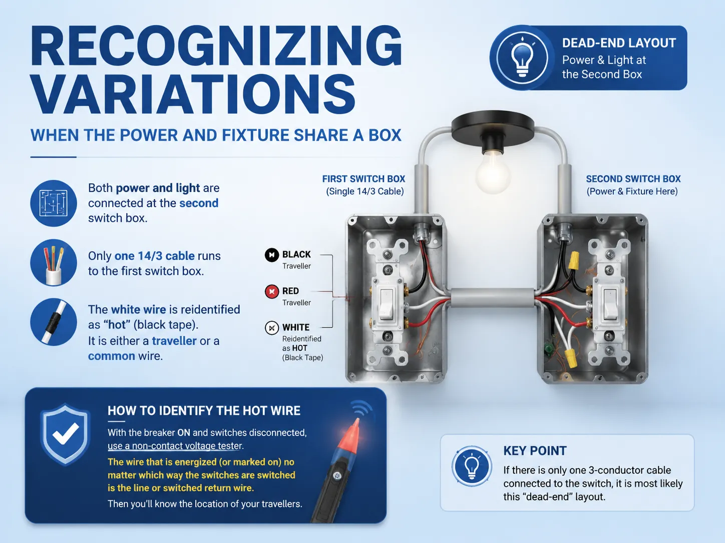
Recognizing Variations: When the Power and Fixture Share a Box
Mike had a “dead-end” layout for the wiring to his hallway. In this scenario both the power and lights are connected at the second switch box, and only one 14/3 wire (cable) is run to the first switch box. Within that wire, the white wire is reidentified as a “hot” wire by marking it with black electrical tape; it is either a traveller or it is a common wire (depending on the exact variation of how the switches were wired). These are the types of situations that many of the 3 way switch wiring diagrams purchased from a hardware store do not accurately reflect. If you have opened a switch box and there is only one 3-conductor cable connected to the switch, it is most likely the above described layout. To determine which wire is always “hot”, use a non-contact voltage tester with the breaker on and the switches disconnected from the circuit. The wire that is energized (or marked on) no matter which way the switches are switched will be the line or switched return wire; you will then know the location of your travellers. If the circuit still refuses to work, refer to our step‑by‑step installation guide on how to replace a light switch for the safe disconnection and identification procedure.
Old-School Methods: Working with Legacy Wiring Systems
Electricians utilized a switch leg where old, white was switched through to the switch box. Black was swtich to the switch and switched through the light fixture with the red wire. These old systems are now code violations for new construction since 2011 when code changed to require neutrals in switch boxes. Many people still have old wiring in their houses that were built before the change. When identifying the old wiring, look to connect whe white wire to a common screw and where the traveler switch is connected to a switch other than a common screw. Re-identifying an old white wire with black tape or red tape at both ends is required when upgrading to GOG Electric new 3-way switches, mark the wire prior to removing any connections. Use a volt meter and continuous test of the circuit before determine which wire is hot.

Common Errors and How to Spot Them Quickly
An example in Austin had Mike making the mistake of connecting a common wire to a traveller terminal resulting in only being able to turn on the light if the downstairs switch was in the appropriate position; leaving the upstairs switch dead (the classic sign of the wiring error). Another common wiring error is to swap the two travellers at one of the switches; this will still allow the light to turn on, but the toggle positions will not be “synchronized” — i.e. both toggles in the down position will indicate that the light is on and in the up position will indicate the light is off; this is contrary to what most people think. A more dangerous wiring error is forgetting to mark a white wire previously used as a hot; someone could later attach it to the neutral bar and create a short circuit. All of these wiring errors are common to make but are also simple to correct when you understand how the common terminal works. Our article on top-rated smart light switches includes models that simplify 3‑way wiring significantly by using wireless communication, eliminating traveller wires altogether.
Tracing the Constant Hot Conductor
The always-hot wire has a constant power supply with the common terminal of the switch. In a standard wiring setup an always-hot wire would be black entering at Switch 1. With a dead-end configuration, the always-hot may re-identify itself using the white wire. The always-hot wire may be identified by switching the breaker on (with great caution to not expose any conductors) and then checking with a noncontact voltage tester. The always-hot will beep regardless of whether either Switch is in the ON or OFF position and must be connected to one of the common terminals. The other common terminal of the switch at the far end of the circuit delivers electricity to the light fixture. Remember that this is the most crucial rule of any 3 way switching diagram.
Why GOG Electric Switches Make 3‑Way Wiring Easier
Mike eventually replaced his original generic switches with GOG Electric’s 3 way switches. He said the fact the terminals on our switches have the words “COM” and “TRAVELER” clearly laser-etched into the back, and the common terminal has a dark screw that is obviously different than the brass-travelers, was a huge relief to him. Every GOG 3-way switch has a clear one-page wiring diagram included that explains both standard and dead-end configurations, and our technical support staff is located in the US and answers in under 2 minutes — no chatbot and no hours of being on hold. Our switches are built for the real world where wire colors fade and boxes are cramped, because we have spent decades in the real world.
Frequently Asked Questions
Which wire goes where on a 3-way switch?
The dark-colored common terminal connects your hot (the incoming wire) or your outgoing wire to the light on every three-way switch. The connections between the two three-way switches are made with the two traveller’s wires connecting to the two brass traveller’s terminal’s on the switch. The ground wire is wired to the green screw. Which traveller’s wire gets connected to which traveller’s brass terminal does not matter.
How were old 3-way switches wired?
Prior to recent years, “switch-leg” wiring may have been used with the use of one conductor, typically a white wire with black electrical tape on both ends. This wire carried either 120V or 240V power (a hot or switched-hot wire), and did not require the use of a neutral conductor in the switch box. When these installations were allowed, there was no violation of the National Electrical Code (NEC); however, installations since adoption of the NEC have not been allowed to have a neutral in a switch box.
However, most switch operation functions will remain the same; however, the total number of wires (conductors) that make up the switch and circuit in accordance with current code and regulations will be different from the original installation.
What happens if I wire a 3-way switch wrong?
A typical issue arising from double pole switches involves having both switches together in the same position, however, if one switch is turned off, the lights will not turn on. This usually happens because the hot leg is connected to the traveler terminal. A reverse polarity may not trip the breaker or short circuit; rather it simply makes that part of the system nonfunctional until all circuits are correctly wired to their corresponding terminals.
Which wire is always hot on a 3 way switch?
The always-hot wire is the conductor that carries power from the service panel to the first three-way switch in a circuit. The always-hot terminal will connect to the common terminal of the first three-way switch. The common terminal of the second three-way switch will have the switched-hot wire going to the light fixture. You can use a non contact voltage tester to identify the always-hot wire. This wire will be live or energized regardless of either three-way switch position.
A correct 3 way switch wiring diagram is a map, not a one‑size‑fits‑all solution. The house you’re working in may have been wired in 1955, 1995, or 2025, and the wire colors and paths will reflect that. Start by identifying the always-hot, then match the common and traveller terminals accordingly. If you hit a wall, remember Mike’s story: a five‑minute phone call with someone who understands the diagram, not just the picture, can save you hours of frustration.