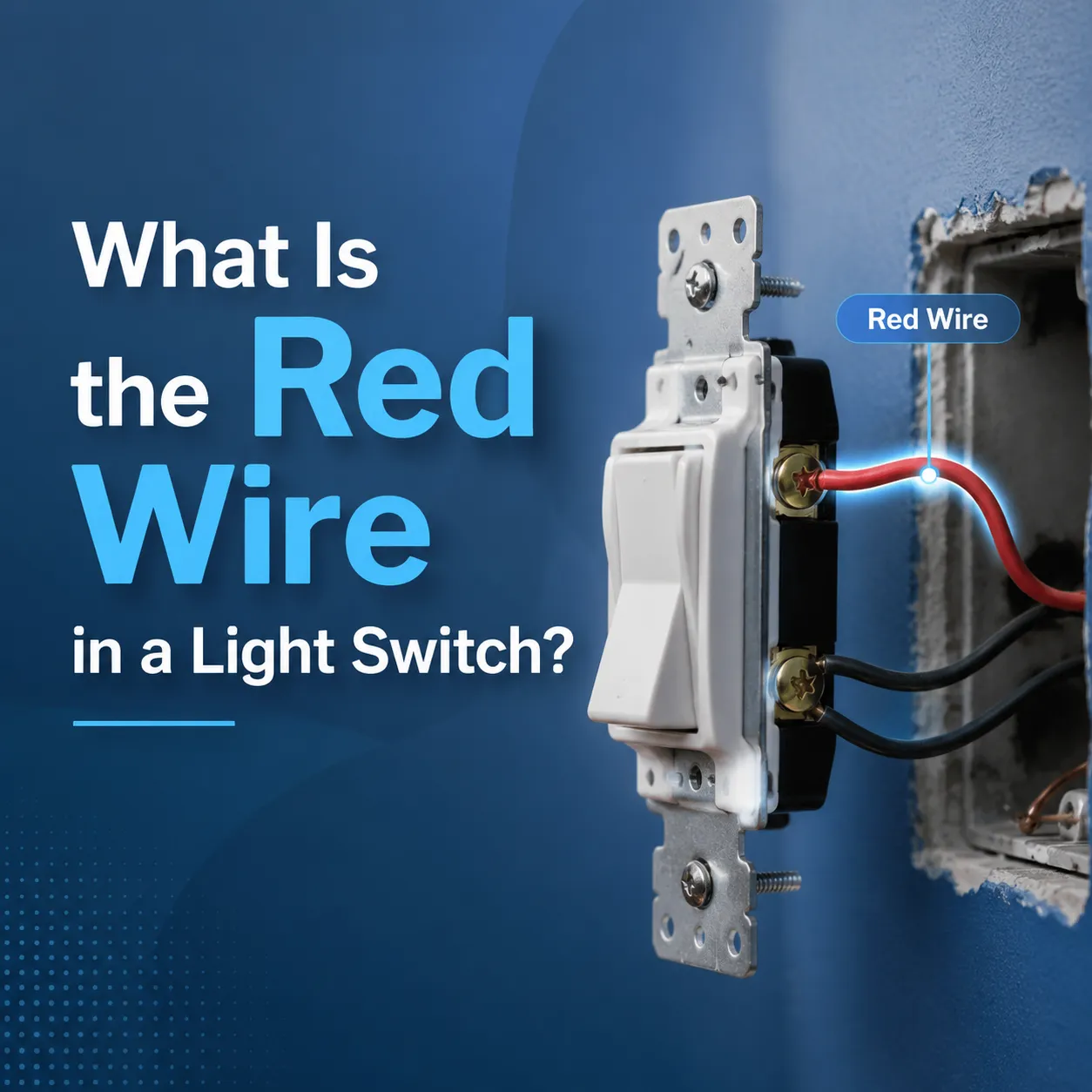
The homeowner in Sydney was intrigued and perplexed when he discovered three wires upon pulling out an old light switch from the wall. While he was familiar with the presence of a black and white wire, he could not understand the purpose of the red wire. The homeowner’s dilemma was indicative of the fact that a red wire in a light switch is usually associated with a traveller wire in a three-way (two-way in North America) lighting circuit, or in some cases, a switched live traveling from the switch to the light fixture.
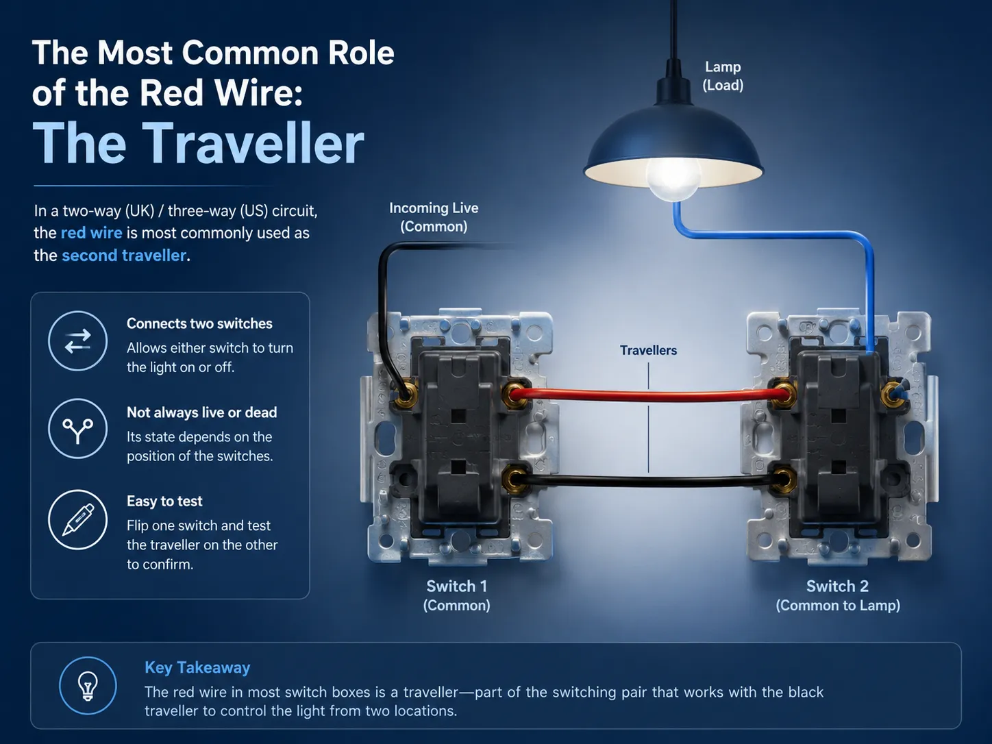
The Most Common Role of the Red Wire: The Traveller
Most residential switch boxes that contain the color red conductor have the red wire as a traveler. The traveler is one of the two wires which connects two switches controlling the same light, referred to as a two-way circuit in UK/IEC and as a three-way circuit in America. The two traveler wires connect between two switches, allowing either of them to turn the light on or off regardless of the state of the other. The red cable is mostly used as the second traveler, while the black cable is used as the other traveler or common. In a two-way (three-way) circuit, one of the switches gets the incoming live at the common terminal while the common terminal of the other switch connects to the lamp. The two traveler terminals are connected by the traveler wires in each switch. The red wire, therefore, is not always live or always dead; it is part of the switching pair that provides its state depending on the switches’ position. If one of the switches is flipped with the help of a voltage tester, the traveler on the other switch is confirmed.
Other Possible Roles: Switched Live and Beyond
In the older wiring technique of a single-pole switch loop — which is not compliant with the building codes currently in effect although employed in millions of homes — the red wire may be responsible for carrying the current needed for activating the bulb. In this system, constant electricity flows into the switch through the black wire, while the red wire returns the switched power. The red wire is a live wire, but it starts carrying the current only in the ON position of the switch. This technique is prevalent in some older homes in North America that used current-less wiring (white and black wires) with the white wire being the hot one now, and the three-wire system (black, red, white) being used for a switch loop.
In a multi-gang box—a container accommodating multiple switches—the red wire is capable of isolating a current from one switch to the other or supplying power to some other circuit. The red wire may also be supplying continuous power through a different phase as a part of a multi-wire branch circuit. Therefore, it is important to understand that color is not the only mean to identify the function of any wire; the use of a voltage tester and the wiring diagram is the only unambiguous way to determine wire characteristics in every particular situation. The National Fire Protection Association (NFPA), with the reference to the National Electrical Code (NEC), provides rules concerning the needed colors of grounded wire but does not set any requirements regarding red, black wires, or any other ungrounded wire types except for the statement that every charge-carrying wire must be identified.
What the Other Colours Mean in a Light Switch Box
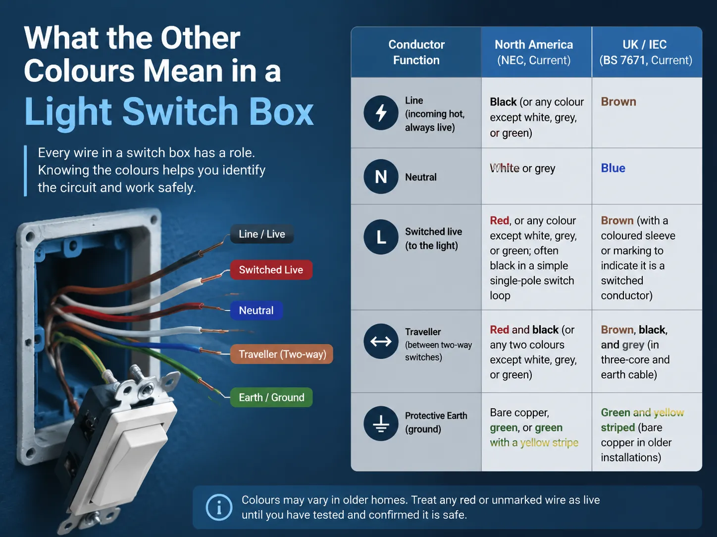
The red wire does not exist in isolation. Every conductor in a switch box has a defined role, and the colours — while not universal across all countries and eras — follow conventions that help a careful electrician identify the circuit. The table below summarises the standard wire colours in residential single‑phase switch boxes in the two most common international systems.
| Conductor Function | North America (NEC, Current) | UK / IEC (BS 7671, Current) |
|---|---|---|
| Line (incoming hot, always live) | Black (or any colour except white, grey, or green) | Brown |
| Neutral | White or grey | Blue |
| Switched live (to the light) | Red, or any colour except white, grey, or green; often black in a simple single‑pole switch loop | Brown (with a coloured sleeve or marking to indicate it is a switched conductor) |
| Traveller (between two‑way switches) | Red and black (or any two colours except white, grey, or green) | Brown, black, and grey (in three‑core and earth cable) |
| Protective Earth (ground) | Bare copper, green, or green with a yellow stripe | Green and yellow striped (bare copper in older installations) |
The colors may vary in older residences. Homes constructed in North America prior the year 1960 may use the color red or black as a hot color while using the white color as neutral wire or hot color dependent on the switch loop design. Similar to the North American homes built prior to year 2006, UK homes used the colors red for live wires and black for neutral. Our informative article that explains the wire colors used in UK countries discusses how wire color changed to uniform brown and blue. Whenever you see a red wire in your switch, you should assume it to be a live conductor and treat it as such.
How to Handle a Red Wire During a Switch Replacement
When performing the replacement of a light switch that has a red wire, it is best to follow a stringent step-by-step procedure that requires one’s patience. Start by turning off the circuit breaker and ensuring that there is no electric current present in the wires in the box using a non-contact tester. Take pictures of the wiring as it is arranged before disconnecting everything because they will be the most helpful reference for one to have. Note which terminal each wire is connected to. In the case of a two-way switch, there will be one terminal that is either dark or marked. The two traveller terminals will be brass. Hence, it can be concluded that the red wire is likely on one of the traveller terminals. If it is connected to the common terminal, then it can mean that it is either the switched live or the live wire going into the switch that is to be replaced. Finally, connect the new light switch the same way as the old one keeping the red wire on the traveller terminal. If the new switch has different terminals, check the manual provided by the manufacturer.
In case you encounter a situation where you are not sure how to use a red wire, it is best to halt any activity. A qualified and licensed electrical professional will be able to guide you on how to operate a red wire properly using such devices as voltmeters and multimeters, and paying the specialist for an hour’s job will be much less costly in comparison with a damaged switch or tripped breaker. For a broader look at the different switch types and their terminal configurations, our article on different types of light switches covers single‑pole, three‑way, and four‑way devices in detail.
Frequently Asked Questions
What to do with red wire when installing a light switch?
In case the red wire has been connected to a terminal on the previous switch, it must also be connected to the corresponding terminal on the new switch. In a two-way (three-way) circuit, it is most likely that the wire serves as a traveler wire and should be connected to either of the traveler terminals. Always take photos of the old wires before disconnection.
Can I connect red and black wires together?
Only when the wiring diagram for your specific installation explicitly requires it. The red and black traveler wires are never connected in a standard two-way circuit (three-way). They run independently from the two switches. Connecting them would cause a short circuit in some switch positions.
What should I connect the red wire to?
You should connect the red wire to the terminal in which it was connected with the old switch for a traveler terminal to the traveler terminal in the new switch. If it was connected in the common terminal, connect to the common terminal in the new switch. Don’t make any mistakes.
Where does the red wire go on a light?
The red wire usually links to the live terminal of the light co, passing switched electricity from the switch to the lamp, in a switch loop. The red wire is not connected straight to the luminaire in a regular two way (three way) circuit, as it is one of the traveller wires that travels between the two switches.
References
- NFPA 70 (National Electrical Code) — Article 200 and Article 310. Requirements for conductor identification and colour coding in North American wiring. National Fire Protection Association.
- BS 7671 — Requirements for Electrical Installations (IET Wiring Regulations). The UK national standard for wiring, including conductor colour identification. Institution of Engineering and Technology.
- Leviton — Residential Light Switch Installation Guides. Manufacturer wiring diagrams and colour‑code guidance for single‑pole and three‑way switches.
- Family Handyman — Understanding Electrical Wire Colours. Practical homeowner guidance on identifying wire colours and their functions in residential switch boxes.
A red wire in a light switch is most commonly a traveller in a two‑way circuit, and its role is to carry the switching signal between the two control points. It may also be a switched live, a constant hot, or part of a multi‑wire branch circuit. The colour alone does not tell the full story — a voltage tester, a photograph of the original wiring, and a clear understanding of the circuit’s configuration are the tools that identify it definitively. GOG Electric’s switches are designed to make that identification clear, with labelled terminals and wiring diagrams that take the guesswork out of connecting the red wire — and every other wire in the box.