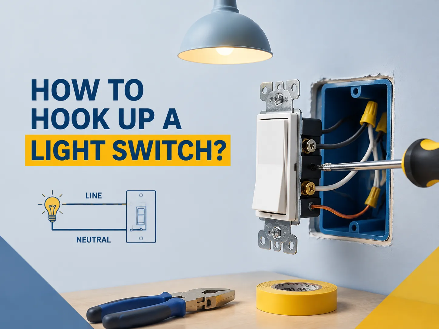
Installing a light switch is one of the most popular electrical projects in every house and also the one that is performed erroneously by most people. Luckily, a single-pole switch requires just three wire types (line, load, and ground) so that by following the instructions in this article one will be able to replace or install one in less than an hour. It explains how these wires connect together, what each wire type does, and how different kinds of switch affects the wiring.
Short answer: In order to connect a single-pole switch, turn off the circuit breaker and confirm that there is no power; find the black (live) wire and the black/red (load) wire going to the light bulb; connect the two to a brass terminal; connect the ground wire to the green screw (or the box); keep the white wire in the box unconnected; then tuck the wires back into the box, attach the switch, and turn on the power.
Anatomy of a Light Switch Wiring Job
In a regular switch box, you will find several wires, all varying in color and use.
| Wire | Color (US/NEC) | Role | Connects to |
|---|---|---|---|
| Line (hot in) | Black | Brings power from the breaker panel | One brass terminal |
| Load (hot out) | Black or red | Carries power to the light fixture | The other brass terminal |
| Neutral | White | Returns current to the panel; does not connect to a standard switch | Nothing (stays spliced in the box) |
| Ground | Bare copper or green | Safety path for faults | Green screw or metal box |
The major point that a beginner needs to understand is that a regular switch is basically an interruption to the hot wire. The hot wire is broken by the switch and the light wired to it is switched on and off, whereas the white wire simply passes through the switch box to the fixture. This means that connecting a switch involves three wires and not five.The types of light switch guide shows the full family of switches, from this basic single-pole to three-way, four-way, and dimmer designs.
Safety First: What to Do Before Touching Anything
Every electrical wiring job begins in a systematic way, which is why injuries often occur when someone does not take the necessary precautions:
- Turn off the appropriate breaker. This means that the circuit feeding the electrical box must be switched off, and not just the lights themselves. If you are unsure which breaker to turn off, disable the whole circuit — it is better to be inconvenienced than to be hurt.
- Confirm there is no current present. You will want to check wire with a voltage tester or a multimeter. The position of the switch is irrelevant to the tester. Should it turn out that the tester shows that there is no power, turn off the appropriate breaker and proceed.
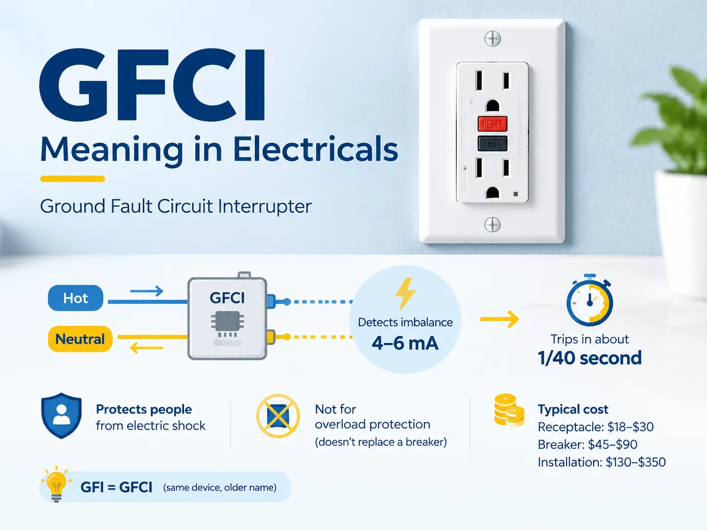
- Work without moisture. There should be no body of water anywhere close, and your hands must be dry. For outdoor and bathroom electrical boxes, check to see whether the circuit is controlled by a GFCI breaker.
- Check the wire gauge. A 15-amp circuit uses 14-gauge wire; a 20-amp circuit uses 12-gauge wire. New switches have to be rated for the circuit (for example, a 15A switch must be used for 15A circuit).
If you open your electrical box but happen to find aluminum wires, worn-out insulation, or a box overloaded with wires, it would be better to stop and hire an electrician as DIY switching would not solve the problem in this case. The common switch problems guide lists the warning signs to look for while the plate is off.
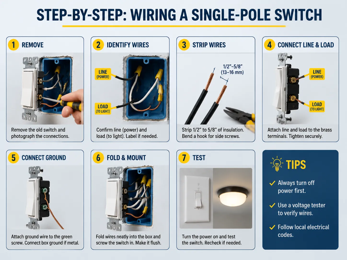
Step-by-Step: Wiring a Single-Pole Switch
Once you’ve made sure the power is turned off, here’s what you need to do next:
- Take the old switch out. First, take the plate off, then unscrew the switch. Use the mounting ears to gently pull it out. Take a picture of the wires so you know how to connect them back later.
- Identify the wires. Use a voltage tester and figure out which of the two wires is the line and which one is the load. Write the names on the wires.
- Strip the wires. Strip about an inch of the copper wire to expose it. Take the end of the copper wire and create a small hook. The wire needs to go around the screws in a clockwise direction.
- Connect the wires. Connect the wire that comes from the power supply to one of the screws and the load wire to the other one. If it is a single-pole switch, you can connect them freely.
- Connect the ground wire. The ground wire can be connected to the switch. You may also create a connection between the switch and the metal panel of the box.
- Fold the wires together. Fold the wires and insert them back into the wall, put the plate on, and reconnect the switch.
- Test the circuit. Turn on the power and switch the light on to see if it is working. If it doesn’t come on, then switch everything off and check whether you have connected the wires correctly.
For a step-by-step visual of the same job with the old device removed, the light switch replacement guide walks through the identical process with more detail on each screw.
Which Wire Goes Where (Color Guide)
Wire colors are your map, and they are standardized by the NEC in the US (with UK/BS 7671 colors differing, as covered in the UK wire colors guide):
- Whether the wire is black or red, both denote hot. Hot wires can either be a power source (line) or a power supply (load) leading to the fixture.
- White = neutral. Notably, older switch boxes might not come with any white wires since anything before 2011 only contained hot wires. If present, white wires are connected together and pushed in the back of the box instead.
- Bare copper or green = ground. This is always connected to the green screws.
- One color confusion that plagues DIY enthusiasts relates to which wire goes at the top and which one goes at the bottom. When it comes to the single-pole switch, however, it does not matter as the brass terminals are all equal. However, you need to make sure that the line is located on one terminal and the load on another terminal and that you never connect the two hot wires to the same terminal.
How Other Switch Types Are Wired
Most homes are equipped with a single-pole switch, although “hook up a light switch” might sometimes denote a more complicated task.
| Switch Type | What It Does | Wiring Difference |
|---|---|---|
| Single-pole | One switch controls one light | Line + load, either brass terminal |
| Three-way | Two switches control one light (staircases, hallways) | Common (dark screw) + 2 travelers; travelers swap between switches |
| Four-way | Three or more switches control one light | Sits between two three-ways; 2 in / 2 out travelers |
| Dimmer (single-pole) | Adjustable light level | Same as single-pole, plus compatible load type (LED/incandescent) |
In three-way and four-way setups, the travelers allow for two different paths for current, which means that connecting a traveler to the incorrect screw will lead to a switch that is only functional at one end. Therefore, it is advisable to read the appropriate guide prior to starting your job and label all wires when removing the old switches. For dimmers, the wiring is identical to a single-pole switch, but the load compatibility question — LED vs incandescent — decides whether it will work quietly or buzz and flicker; the LED dimmer compatibility guide covers that check.
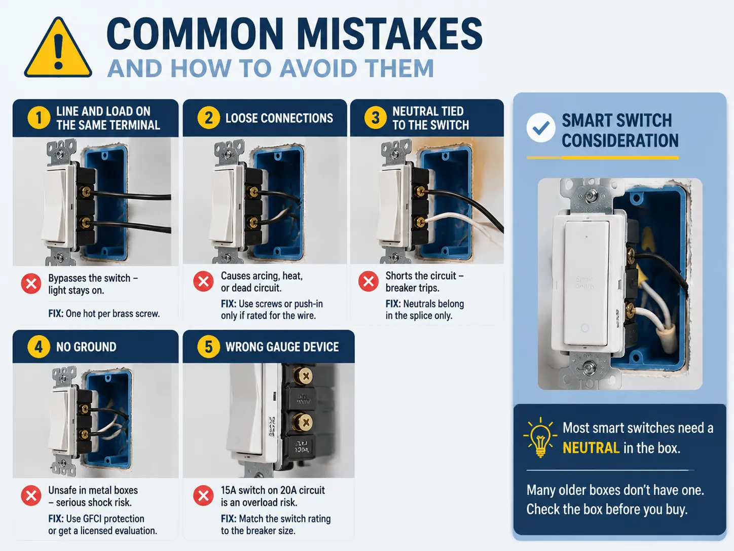
Common Mistakes and How to Avoid Them
In terms of errors in this field, they almost always pertain to mistakes in the wiring process, and some of the most common flaws are as follow:
- Line and load connected to one terminal. This makes it possible to skip the switch altogether, meaning that no matter what is done to the switch, the light stays on all the time. Solution: connect one hot wire per screw.
- In case of loose connections. Here, a wire is inserted under a screw while not having any hook secured that could make the connection firm, or in case of backstab failing to rest on the connector, this will result in arcing, heating up of the wire, and ultimately, a failure or loss of circuit service. It is recommended to use screws only, or to plug in wires in push-in connectors only in those cases when their diameter is meeting the specifications provided by the device.
- Neutral connected to the switch. Connecting the white wire with brass terminal is making the circuit burn out, as the circuit breaker cuts the power immediately after it starts. The neutral should be found only in the neutral connection.
- Absence of the ground wire. In the standard cases, there is no chance of having this wire at all. In the case with a metal box and a cable with no ground, the safest variant would be to select a GFCI-protected circuit instead of the floating switch.
- Wrong device gauge. If a 15 amp switch is placed on a 20 amp circuit, this presents a risk of an overload. Make sure that you know the ampage of your circuit breaker before buying the replacement.
- In case you are thinking of using a smart switch, it should be mentioned that you will also need to rewrite the wiring, as most smart switches involve using a neutral wire in the electrical box while older electrical boxes usually do not provide for such types of wires.
FAQ
Which wires go where on a light switch?
On a typical single-pole switch, you connect the hot black wire from the panel (line) to one of the brass terminals, and the black or red wire going to the light (load) to the other brass terminal. The ground wire is usually copped bare on the green color screw. Whites are kept separate in the box and does not connected to the switch. If you’re setting up a three-way switch, the line will be connected on the common (dark screw) and the two traveler wires will be connected on the two brass terminals.
How do you wire up a light with a switch?
You need to run two conductor wires from the power source to the switch box and a new wire from the switch box to the light. Connect the black wire going to the line in the light switch to one of the terminals in the switch box, then connect the black wire of the load going to the light to the second terminal of the switch. In addition, connect all connections together and wire up the ground wire. This completes the light switch connection while the neutral wire connects directly to the fixture.
Does the hot wire go on top or bottom of a light switch?
On the single-pole light switch, hot wire can be connected on any of the two terminals; they are electrically the same. However, when it comes to three-way light switch, terminal plays an important role. You must always connect the load/line on the common terminal screw and the traveler wires on the traveler brass terminals.
What color wires go where on a light switch?
The hot wire (black/red) is connected to the brass terminals, one for the line, another one for the load. In addition, the ground wire (copper/green) goes to the green terminal. White wires do not connect to the switch; they get connected to each other using a wire nut. In cases where other colors are used, they must be identified first by a tester.
References
- Family Handyman — How to Wire a Single-Pole Light Switch
- The Spruce — How to Wire a Light Switch
- This Old House — Wiring a Light Switch
- Home Depot — How to Wire a Light Switch
Conclusion
When it comes to connecting a light switch, one common theory states that a switch actually breaks the connection in the hot wire. First, you will identify the black wire and the black or red load wire, and connect them to the opposite brass terminals of the switch. Don’t forget to ground everything and keep the white wires connected, and you’ll be good for many years. The sequence of achieving safety here is very important: switch off the breaker, make sure that there is no electricity, and then test the switch.
Mistakes are usually rather basic: having two hot wires on one terminal, having a neutral on brass, and then wrong grounding.